Cap upgrade Conion c100f then not working

keeney123

Member (SA)
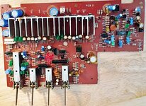
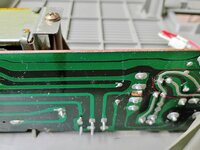
Started new thread after upgrading Boombox. This is what happens if one does not recheck all the capacitor value and direction before powering it up. Last year I did this and found a capacitor in backwards in the output amplifier circuit to the speakers.

Also, I want to ask caution where is the ground screw in the back panel as I cannot find one? Never mind I found it. Need to put glasses on. The black twist on knob. Looking fo a actual screw. My mistake.

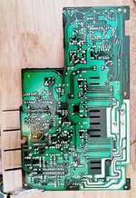
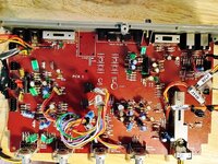
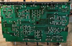
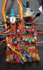
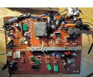
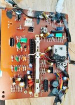
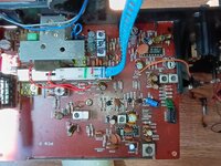
Anyway, I have opened the unit and attached a picture of the open unit.
 

Attachments

  • conion c100.jpg
    conion c100.jpg
    189.9 KB · Views: 20
Last edited:

keeney123

Member (SA)
Finished amp board. Found two other caps backwards and one cap wrong value. Replaced them with new caps. Have attached top and bottom side picture of amp board. Upper right-hand corner is c233 which is not on the capacitor sheet. I believe it is a 47uF 10 v. Will have to verify on the schematic.
 

Attachments

  • Top amp board.jpg
    Top amp board.jpg
    215 KB · Views: 12
  • bottom of amp board.jpg
    bottom of amp board.jpg
    213.8 KB · Views: 11

Tinman

Member (SA)
Yep, you have to double check everything as you go or you end up doing what you're doing, which blows.
Not all boards are the same, some highlight the positive leg and others the negative leg.
You can draw a picture of the way that particular box signifies positive and negative so you have a reference as you go.
I've done numerous boomboxes and just did a clock radio yesterday that only had about 20 caps.
I still double checked every one as I went.
When I did a box, I'd do one board at a time and write down every cap's value and put a mark on top of it after it's written down.
I lay my caps out from smallest to greatest value.
I keep a magnifying glass nearby also, just in case I question something (is it 47 or 4.7).
It can get confusing.
 
  • Like
Reactions: BoomboxLover48

caution

Member (SA)
Yeah, C233 is 47uF @10V. It's part of the alarm's voltage regulator circuit, dampening inrush current and ensures Q203 gets a steady voltage. It also creates an RC filter with R235, providing ripple rejection (main power comes in on the other side of R235)

1780814736688.png
 

keeney123

Member (SA)
Yep, you have to double check everything as you go or you end up doing what you're doing, which blows.
Not all boards are the same, some highlight the positive leg and others the negative leg.
You can draw a picture of the way that particular box signifies positive and negative so you have a reference as you go.
I've done numerous boomboxes and just did a clock radio yesterday that only had about 20 caps.
I still double checked every one as I went.
When I did a box, I'd do one board at a time and write down every cap's value and put a mark on top of it after it's written down.
I lay my caps out from smallest to greatest value.
I keep a magnifying glass nearby also, just in case I question something (is it 47 or 4.7).
It can get confusing.
The direction of the picture of caps on the boards are all like the photo attachment. With the white of the circle being the negative leg and the board color of the circle, light brown, being the positive leg. All caps I have use have a shorter leg for negative and long leg for positive. The short leg, negative corresponds with the black strip of the cap. I do not see any differences on these boards or difference on the caps with short leg negative and black strip. I understand in some instances the black strip can mark the difference between electron flow and hole flow. This is the difference on how an electrical engineer understand the current flow as holes or positive flow and how an electronic technician is taught of electron flow or negative flow. Electrons being about 1300 times lighter in weight the protons it would seem that the electrons are flowing to the positive. However, Electrical Engineers see the absents if electrons as positive flow. If I am wrong, please correct me.
The other problem that makes it difficult for me is I have macular degeneration. I have not big magnifying glass, and I just use reader glasses with a flashlight.
When I was a technician working for Gerber Scientific Products, we used to have a minimum of 2 problems for every board that came through. That is 70% of the boards that failed on initial test had at least 2 problems. We could have anything from 20-ohm shorts caused by dust on the print they use to make the board to solder shorts to legs not put in socket to chips put in backwards. How team of technicians and electrical/ electronic engineers got the time to test and repair a board down to 20 minutes a board. Each board have 90 ICs including processor, Rom and Ram ICs, multiply transistors and photo optic transitions. The boards then went to QC that ran a 72-hour test on the units. We had 3% fall out in QC which we repaired. Once in the field there was less than a 1% fall out. Our service technician would fix those.
 

Attachments

  • cap direction.jpg
    cap direction.jpg
    36.1 KB · Views: 6
Last edited:

keeney123

Member (SA)
Yeah, C233 is 47uF @10V. It's part of the alarm's voltage regulator circuit, dampening inrush current and ensures Q203 gets a steady voltage. It also creates an RC filter with R235, providing ripple rejection (main power comes in on the other side of R235)

View attachment 62289
Thanks, caution, for confirming that. Will save me time. So, this is where they smooth out the DC ripple?
 

keeney123

Member (SA)
In/out board complete. Only one mistake. I put in wrong size cap. Have attach photos of top and bottom of board.
 

Attachments

  • topside of in out bd.jpg
    topside of in out bd.jpg
    274.9 KB · Views: 7
  • backside of in out bd.jpg
    backside of in out bd.jpg
    177.8 KB · Views: 8

keeney123

Member (SA)
Finished upper deck Bd. Only found one problem. The Solder joint that was make to the land run broke. This board runs and pads where different than the other boards. They were not connected to the fiberglass board very well. You can see the rework I had to do on the solder side. The blue circle is where the break happened and I have repair it. The rose circle is not connected but I cut the lead anyway because it was too close.

Wonder if anyone know where to find the fuse 4 Amp. I have circled it in red to the attach portion of the schematic. Only thing I can think is on the bottom side of the main transformer board there is an extra thick run. Perhaps that is fusible at 4 Amps. I have not looked for any zero-ohm resistors that may also be fusible.
 

Attachments

  • 4Amp fuse.jpg
    4Amp fuse.jpg
    138.8 KB · Views: 6
  • upper deck bd top.jpg
    upper deck bd top.jpg
    202.3 KB · Views: 5
  • upper tape deck bd bottom.jpg
    upper tape deck bd bottom.jpg
    210.3 KB · Views: 8

keeney123

Member (SA)
Hi Caution,
That fuse is for the AC input to the transformer, I believe.

Have attached photo of the power board with a red circle enclosing a curved exposed run. I am wonder if this run is a fusible link that is rated to 4 amps.
 

Attachments

  • power bd bottom side.jpg
    power bd bottom side.jpg
    135.8 KB · Views: 9
Last edited:

caution

Member (SA)
Oh yeah, you're right. The one directly on the AC input, on the transformer board, is a 1A fuse. The one you're referring to is 4A. I forgot about that.

It goes between the output of the rectifier and the alarm switch S2002.

It's not mounted on a PCB, so it doesn't have a reference designator on the schematic like the 1A fuse does (FU801, on PCB8, the transformer board).

It's just along the wire and covered with a clear plastic sheath. Not all units have it though, mine don't. I think I've seen it in photos of other owners.

I can't remember which connector wire it would be on, since the schematic doesn't show connectors.
It's either CN803 (Green/Yellow wires) or CN804 (Black/Red wires).
You'd have to look at which of those four wires connects to the center pin of S2002 on the power switch board.
 

keeney123

Member (SA)
Oh yeah, you're right. The one directly on the AC input, on the transformer board, is a 1A fuse. The one you're referring to is 4A. I forgot about that.

It goes between the output of the rectifier and the alarm switch S2002.

It's not mounted on a PCB, so it doesn't have a reference designator on the schematic like the 1A fuse does (FU801, on PCB8, the transformer board).

It's just along the wire and covered with a clear plastic sheath. Not all units have it though, mine don't. I think I've seen it in photos of other owners.

I can't remember which connector wire it would be on, since the schematic doesn't show connectors.
It's either CN803 (Green/Yellow wires) or CN804 (Black/Red wires).
You'd have to look at which of those four wires connects to the center pin of S2002 on the power switch board.
Thanks Caution. I will look again on the wire. I don't believe I saw one before.
I have done the lower cassette board and saw no problems with the caps. I, however ran into a problem with many wires breaking off including the wire that goes to bd 15 that is the three set of wires and also the white wire. I am trying liquid tape to try and hold the wire by the insulation instead of hanging on by the solder. Many of the single plug test points and so worth I just solder to the post after they broke before when I had opened it last time and I have no crimpers.

One of the reasons I just powered the unit up last time is because I thought I had a fuse on the output of the bridge circuit. I did not physically check where the fuses were. I, like you, assumed the Fuse near the power output plugs was the diode fuse to the bridge circuit that protects the secondary winding.

Live and learn.
 

keeney123

Member (SA)
My solution to wires breaking off on the lower cassette bd. Not pretty but I think it will work. Because of my up-close vision is somewhat bad and I could not guarantee if the traces where shorted or the pads where still there for the ribbon cable wire on the edge of the board. You can see the fix I did for myself. First, I put a solid wire through the holes and solder them to the solder side to pins they went too. I will show this once the liquid tape dries. You can see on the top side in the blue circle the solid wires sticking out above and parallel to the board. I will then stip the ribbon cable and make a sure mechanical connection to these wires and then solder them. I then will cover them with the liquid tape. After that dries I will electrically tape over all three wires. Other parts of the board I have use the liquid tape to fasten the insulation of the wires to the board and metal can. I have tried to be careful to ensure board call out is not covered. However, if it does get covered one can use an x-acto knife to remove it gently. the lettering on board will stay intacted.
It is a far cry from what I use to do in my 40's with better eyesight and a 5-dipole fluorescent magnifying lamp. I used to work on 0.5" x 1" boards attaching 7 26-gauge wires, resistors, MOS FETS and surface mounted chips to the board. This than was put in two gold plated cylinders and potted in place. The front had a point that had be connected to the board. This was used for medical research machines that then inserted them in live cells. These boards operated on a current of 1x10-14 femto amps. I had a 95% success rate to the field. The person I took this over from had a 30% success rate. This was at World Precision Instruments in Sarasota, Fl.
Anyway, none of that matters now because I am in my 70s.
 

Attachments

  • lower cassette bd.jpg
    lower cassette bd.jpg
    230.2 KB · Views: 4

keeney123

Member (SA)
In this reply I have shown the mode that I did on the lower bd both top and bottom. Hopefully it will be more robust than the original. I ended up using just electrical tape on the solder connection of the three wires. First tape center wire than whole piece. This way if wires ever need to be replaced it just a matter of unwrapping tape.

I also show the top side of the tuner board. I have completer checking caps with no problems other than I cannot find where C019 is located on the circuit bd. It must be under the protected area with a fiber board over and around it. I did not remove the board to read the values and see the direction of the cap I had replace. Did not want to have to restring the tuning cord. I have it fixed in place so it will not just fall off, and I want to keep it that way.

Just have two easy boards to do and I will be done. The speaker caps I tripled check and ohm out when I put them in.

I just got in an old fluke multimeter 8027B from an ebay vendor. It works like it did when new. I like the liquid crystal display as one can see it better than many of the new meters on the market. I got it for diode and transistor ohming. The old Automotive meter I have does not do that.

Checked diodes of power supply board in circuit. This gives a rough idea of the circuit. I did not find a completer open circuit. One really has to lift one leg of the diode up to positively verify it is good. I just wanted to verify no catastrophic event did not occur because of a backwards cap. I will really be able to tell when I apply power just to the power supply board.
 

Attachments

  • mode looking back side bd.jpg
    mode looking back side bd.jpg
    196.1 KB · Views: 2
  • mode to stop wire breaking.jpg
    mode to stop wire breaking.jpg
    193.5 KB · Views: 2
  • top side tuner bd.jpg
    top side tuner bd.jpg
    204.2 KB · Views: 3

keeney123

Member (SA)
Does anyone know where this part goes in the Boombox or does it not go in the boombox. It has a number of 2BK0025. Last time I put the unit together I could not find a place for it.
At that time, I was working in the garage of my brother-in-law. He had a habit of put stuff on the table I was working at, so I was not sure it this goes with the unit or not.
One time this black grease showed up and got over everything took a long time to clean it up. I have no idea where it came from.
Now I am working in my apartment and only have to worry about my cat getting into things.
Keeps it interesting.
 

Attachments

  • Bracket 2BK025.jpg
    Bracket 2BK025.jpg
    23.7 KB · Views: 1

keeney123

Member (SA)
I finished checking the caps on the led boards and the mixer level bd. All caps check good. Did not supple photo because these are uneventful to look at. Just note I put some liquid tape on the wire insulation to stop breakage at solder joint.

Power up just with the power board connected and got about 19.3 Volts DC so it looks good to continue assemble and testing.

I will put upper and lower bd in and the Amp bd. I will only connect the Amp bd and see what I get in voltages.

If that seems good, I will assemble to rest of the unit and see if I am able to tune in a FM channel.