Yep, you have to double check everything as you go or you end up doing what you're doing, which blows.
Not all boards are the same, some highlight the positive leg and others the negative leg.
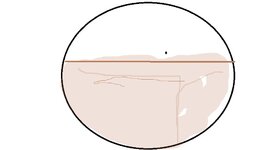
You can draw a picture of the way that particular box signifies positive and negative so you have a reference as you go.
I've done numerous boomboxes and just did a clock radio yesterday that only had about 20 caps.
I still double checked every one as I went.
When I did a box, I'd do one board at a time and write down every cap's value and put a mark on top of it after it's written down.
I lay my caps out from smallest to greatest value.
I keep a magnifying glass nearby also, just in case I question something (is it 47 or 4.7).
It can get confusing.
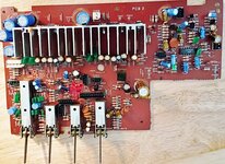
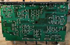
The direction of the picture of caps on the boards are all like the photo attachment. With the white of the circle being the negative leg and the board color of the circle, light brown, being the positive leg. All caps I have use have a shorter leg for negative and long leg for positive. The short leg, negative corresponds with the black strip of the cap. I do not see any differences on these boards or difference on the caps with short leg negative and black strip. I understand in some instances the black strip can mark the difference between electron flow and hole flow. This is the difference on how an electrical engineer understand the current flow as holes or positive flow and how an electronic technician is taught of electron flow or negative flow. Electrons being about 1300 times lighter in weight the protons it would seem that the electrons are flowing to the positive. However, Electrical Engineers see the absents if electrons as positive flow. If I am wrong, please correct me.
The other problem that makes it difficult for me is I have macular degeneration. I have not big magnifying glass, and I just use reader glasses with a flashlight.
When I was a technician working for Gerber Scientific Products, we used to have a minimum of 2 problems for every board that came through. That is 70% of the boards that failed on initial test had at least 2 problems. We could have anything from 20-ohm shorts caused by dust on the print they use to make the board to solder shorts to legs not put in socket to chips put in backwards. How team of technicians and electrical/ electronic engineers got the time to test and repair a board down to 20 minutes a board. Each board have 90 ICs including processor, Rom and Ram ICs, multiply transistors and photo optic transitions. The boards then went to QC that ran a 72-hour test on the units. We had 3% fall out in QC which we repaired. Once in the field there was less than a 1% fall out. Our service technician would fix those.