My rx-5350 won't shut off

Status
Not open for further replies.

BoomboxLover48

Boomus Fidelis
We should do some basic things before we check voltages and trace signal.

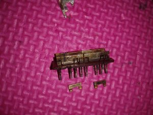
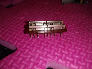
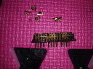
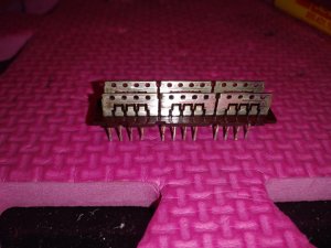
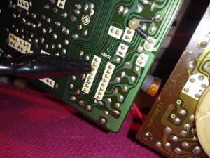
Have you cleaned all the switch contacts including radio/ tape function switch and the long record bar with Deoxit? I would do that. Spray Deoxit and move it a min 20 to 25 times back and forth.
This is something we all do if there is some sort of on off problem.

It seems like the radio section is losing power or audio signal completely and this repeatedly happen in different intervals of time.
 

lazol

Member (SA)
I will sure check the voltages, however i'm always more prone to think about a mechanical failure rather than a failing component, as boomboxlover is suggesting.
I did deoxited everything but i know that sometimes that's not enough: especially with switches it happens that they get really dirty inside and the only way to fix them is desoldering, taking apart and clean.
I'll see what i can do in the next days and post back, thanks for all your inputs!
 

lazol

Member (SA)
Sure they do, no doubt about it.
Today i tried the radio more extensively and i found out the following: on a station that was cutting out every couple of minutes i tried to shorten the antenna from fully extended to fully retracted and guess what? No more cutting out!
I listened for at least an hour to be absolutely sure about that, and it never cut out.
Then i moved the radio to a different location with the antenna in the same position and the cut out started again.
So now i'm reasonably sure that it's a reception issue.
I'll check the antenna connection to make sure it's properly hooked up, but i'm pretty sure it is.
What i think is that the muting system is too sensitive for some reason. I will check Q3,4 and 5 and a couple of resistors and diodes that make up the muting system and report back.
Hope is not an alignment issue... not something i could tackle myself.
 

Fatdog

Well-Known Member
Staff member
Lazol, do you have lead paint in your house? :lol: :lol: :-P All kidding aside, it almost seems like you have some electronic interference going on. I've never encountered it with antenna reception though. :hmmm: :hmmm:
 

lazol

Member (SA)
Fatdog said:
Lazol, do you have lead paint in your house? :lol: :lol: :-P All kidding aside, it almost seems like you have some electronic interference going on. I've never encountered it with antenna reception though. :hmmm: :hmmm:
As far as it's not poltergeist... :lol: :lol:

As the old good proverb says
"When you hear hoofbeats, think of horses not zebras" i'm still suspecting dirty switches.
I'll desolder and take them apart before moving to the tuner board.
I'll do it next week and post back!
 

lazol

Member (SA)
Update:

Ok, so this is one of those project that must not be completed, by contract.
I'll start from the end: i fixed the radio cut off! That was an alignment issue or something realated to the "tuning box"(?).
I realized because when i was putting my hand close to it, the signal was cutting off: the solution was deoxit, turning the screws on top of it to clean it out and put back the screws the way the were before. That worked for me.

But, as i said, i started the job cleaning the switches. They were pretty dirty and i though that cleaning them would have solved the problem.
But not only it didn't, i also lost the fm stereo light!
Now, i don't have ocd, i can totally live with that, but it makes me extremely mad when i just can't find an explanation for what happened...
The fm stereo light was working fine before i cleaned the switches, how come it doesn't work anymore?
The fm stereo signal does come in, i can easily tell, it's just the light that doesn't.
The switches are working fine in all the positions.
I even re-desoldered the switches to make sure the metal tabs were contacting properly and that i soldered back correctly, but nothing.
Does the light need dirty switches to work??
Again, i don't want to invest my time in such a minor issue, but if someone has an idea about what i did wrong please let me know, it would be appreciated!

I attached the pictures of the before/after the (harmful?) cleaning.
 

Attachments

  • 20191021_131546.jpg
    20191021_131546.jpg
    111.6 KB · Views: 11
  • 20191021_132511.jpg
    20191021_132511.jpg
    82.9 KB · Views: 11
  • 20191021_140915.jpg
    20191021_140915.jpg
    99 KB · Views: 11
  • 20191021_141918.jpg
    20191021_141918.jpg
    91.2 KB · Views: 11

caution

Member (SA)
lazol said:
That was an alignment issue or something realated to the "tuning box"(?).
I realized because when i was putting my hand close to it, the signal was cutting off: the solution was deoxit, turning the screws on top of it to clean it out and put back the screws the way the were before. That worked for me.
By tuning box do you mean the large variable cap for tuning stations? Or something else, like chokes?
The FM stereo light is driven by the MPX chip, so if it can't lock into FM stereo it's not going to turn it on.

By the way, the switch has a thin coating of nickel so you have to be careful not to use anything too abrasive. Looks like you might've taken it all off on the corners. Had this happened where the switches slide, this could cause corrosion problems down the road.
 

lazol

Member (SA)
Yes, the circled box.

I used a very light sandpaper (1000), it seems to me that some corrosion were there from before.

The fm stereo does work, it's olny the light that doesn't turn on.


EDIT:
Ok, i think the LED itself must be burned out, i tested it with the multimeter in diode function and it's showing OL in both directions.
 

Attachments

  • Capture+_2019-10-22-15-57-39.png
    Capture+_2019-10-22-15-57-39.png
    372.7 KB · Views: 11

caution

Member (SA)
It's very easy to check an LED, use a battery and a resistor in series with one of the leads, maybe something between 100 and 10k ohms.
 

caution

Member (SA)
Nice to know! So now use the ohm meter to check the connection from the LED cable to IC403 pin 10. Any solder connection along there, PCB trace, or the switch S5, are all culprits. The 5350 also employs printed resistors and wires using carbon and silver paints, to the top side of the PCB, as well as the holes that connect these to the other side of the board. All three of these things could develop an open connection.
 

lazol

Member (SA)
My ic403 has 9 pins.. It's different than in the manual?!
 

Attachments

  • 20191022_213235.jpg
    20191022_213235.jpg
    94.2 KB · Views: 11

caution

Member (SA)
Yeah probably just a mistake, I've noticed a lot of those! It's actually in the corner of the board. The LED line starts on pin 10, goes all the way around the edge of the board, through a wire jumper, and then into pin 3 of a 6-pin cable going to the front panel LED board.

Pin 4, right next door, is the other side of the LED. This goes through load resistor R425 and then onto S5 the mono/stereo/ambient switch. Positions 2 and 3 connect the LED to power for the stereo modes. Position 1 (mono) disconnects the stereo LED and connects to a circuit that when tied to power, disables muting between stations.

48945662677_aa918c80a7_z.jpg

48945719597_e0e8cb1564_h.jpg

48944927028_7c6c27da5b_b.jpg

48945470556_da31ed4f68.jpg
 

lazol

Member (SA)
A BIG thank you to caution for taking the time for such a great explanation!!
I won't tell the all story, it wasn't easy, but at the end i got everything working!
Part of the problem is that the schematic actually does not match my 5350 model (which is 5350F).
The cable that feeds the leds has 5pins only, (the leds are only 3, no dolby system green light) and the ones for the fm stereo lights are not the 3 and 4, as the schematic shows. Also, the pin on the ic403 is not the 10 and all the board printed wiring follows a different route.
I attached some pictures showing this matter. But as i said i ended up figuring it out and i'm glad it's all working now!
Again, thanks to caution for pointing me in the right direction and everyone else who helped!!

P.S: The fm cutting out started again. It is related to the tuning box, it's enough touching it and the sound goes away!
I tried several things this afternoon, all unsuccessful, but the last one was moving out of the way a couple of capacitors that were lying right on the box, and now i'm not experiencing the problem for a long time, and the box itself is much less "sensitive" (now if i touch it the sound doesn't change).
Radio stuff is definitely not my thing, i can only go ahead by attempts...hope i got it this time!
 

Attachments

  • 20191023_105312.jpg
    20191023_105312.jpg
    59.5 KB · Views: 11
  • 20191023_105303.jpg
    20191023_105303.jpg
    121.7 KB · Views: 11
  • 20191023_105212.jpg
    20191023_105212.jpg
    114.1 KB · Views: 11

BoomboxLover48

Boomus Fidelis
The board has some weak areas under stress that can break especially at the corners. I would check for any cracks on the board. Check around the edges and corners.
 

caution

Member (SA)
Glad to hear it's working now! Any idea what was causing the LED not to work?

That's very interesting to see such basic differences between the 5350 and 5350F, they went back to the drawing board and even renumbered some parts, and removed a few features. Or, they did they do F design first, and added in Dolby (and other stuff) later on? It would be interesting to know if there's a service manual for the F.
 

lazol

Member (SA)
I tried looking for that manual but no luck!

Desoldering switches in such old boards is always something i try to avoid if possible: even if you pay attention it's an invasive task.
As boomboxlover48 said, i broke the led track right on top of the function switch i desoldered, probably when i pushed it up.

The fm cut off issue is not resolved, it is much better tho: radio can play for long periods without cutting off now, but it will eventually.
It's 100% a tuner board problem, i think it's not possible to recap it without messing up with the tuning cable, isn't it?
 

BoomboxLover48

Boomus Fidelis
A complete recap was done on a 5350 by member blu_fuz. Replace the caps one at a time watching polarity. In my case I cover the area with folded paper where there is chance for the solder to touch the tuning cord, and be extremely careful. I've worked on tuner cord replacement on so many tube radios and boomboxes like Sharp GF777. Don't be afraid, but be super alert when the soldering iron comes close to components.
 

lazol

Member (SA)
So I finally got the chance to take apart the tuner board and performed the following:

- desoldered and cleaned the band selector switch.
- check for cold solder joints and resoldered a couple of suspicious ones.
- removed a good amount of vax that was surrounding a bunch of components, including the tuning box (interfering with the reception?).
- a general cleaning.

Now, after a couple of days of consistent use, i can confidently say that the radio is working fine and the cut off problem is gone!
Unfortunately i couldn't perform a step by step troubleshooting process, so i'm not sure of which was the task that effectively got rid of the issue, but i still hope this thread may help someone else in the future!

A big thank you to everyone who tried to help! A special thanks to member caution for the detailed circuitry explanation and BoomboxLover48 for encouraging me to don't fear messing up with the tuner dial cord (which i obviously did, but was able to put back in place after all :thumbsup: )!!
 
Status
Not open for further replies.