Big Ben deck playback too fast
- Thread starter docs
- Start date
You are using an out of date browser. It may not display this or other websites correctly.
You should upgrade or use an alternative browser.
You should upgrade or use an alternative browser.
- Status
- Not open for further replies.
Looking at the sample schematic, it appears that if the .1uf cap is shorted, the motor would run full unthrottled speed. It also appears that the ground side of motor windings should enter IC through pin 3 and thereby grounded through pin 2 of that IC. If the IC is working properly, it should be throttling the motor through those 2 pins. If you check resistance from the ground side of motor to ground, are you getting 0 ohms? Because if you are, then no wonder the motor is running unchecked.
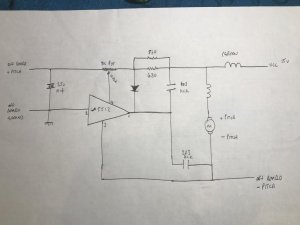
Can you map out that PCB and draw a little diagram based on the components so we can see. Those images of the top side with the components doesn't really tell us anything. With just a handful of components, it shouldn't be too hard.
Can you map out that PCB and draw a little diagram based on the components so we can see. Those images of the top side with the components doesn't really tell us anything. With just a handful of components, it shouldn't be too hard.
See the motor (-) and how it's connected to the off board (-) pitch? Any chance that the off board pitch connection is shorted to ground? Just check resistance from that wire to ground.
Also another possibility comes to mind is whether pins 2/3 of that IC is shorted. It should throttle the motor. However given the persistence in your problems and the very low ohms readings between motor - and pcb ground, this makes me think maybe there is a ground connection allowing motor to operate and bypass completely the la5512 control. Note, by "motor" ground, I am not talking the motor assembly including circuits, I am talking motor "only" as it appears in you drawing sans circuitry.
Also another possibility comes to mind is whether pins 2/3 of that IC is shorted. It should throttle the motor. However given the persistence in your problems and the very low ohms readings between motor - and pcb ground, this makes me think maybe there is a ground connection allowing motor to operate and bypass completely the la5512 control. Note, by "motor" ground, I am not talking the motor assembly including circuits, I am talking motor "only" as it appears in you drawing sans circuitry.
I dont think so Eric, only thst it supports pitch control.
I've got the circuit back together and testing the -pitch lead to the power lead ground on the main pcb gives weird accumulating readings and no steady resistence reading.
Reading resistence between the -pitch lead and the ground on the motor (next to it) also doesn't result in a static reading.
I've got the circuit back together and testing the -pitch lead to the power lead ground on the main pcb gives weird accumulating readings and no steady resistence reading.
Reading resistence between the -pitch lead and the ground on the motor (next to it) also doesn't result in a static reading.
Dave, I don't understand how you are doing the test. My suggestion was that you disconnect the off board -pitch wire (from the point as labeled on your drawing) and test that against main ground. This does not have to be performed while running. If your test was to probe that point with an ohmmeter, as the motor is running, then that point itself surely should be fluctuating to a point if the IC is working properly which suggests that it is "controlling" the motor. In fact, if you were to grab part of the rotating assembly or somehow manually introduce friction thereby forcing the motor to work harder, you may even see lower resistance as the controller attempts to allow more current to pass.
Without a clear understanding of how you are performing your test, I am having trouble picturing it.
Without a clear understanding of how you are performing your test, I am having trouble picturing it.
Ok apologies, I've just redone the test.
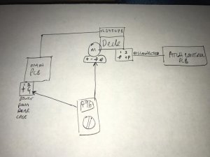
With power off I have the 2pin lead going to the pitch control board disconnected from the rear of the deck. One probe is placed on the -pitch connect point where the lead solders to the motor pcb and the other is on the ground pin of the two pin power connector on the main pcb.
This lead to a 496Ohm steady reading.
Ok, I'm still not entirely clear. See if this makes more sense and if this is what you did.

Don't forget that YOU are working with the boombox in front of you. WE are working only with what we see in this thread. So while things might seem quite clear in your description to you, it may not be so clear to us viewing this thread, especially when you speak of 2p connectors, etc. Because nothing in this thread shows us where is the 2p and what it is connected to and what end we are speaking of.
Oh, one final thing. Do this test NOT POWERED UP, not plugged in.
This really should not be so hard and I'm not sure why we are on different planets.
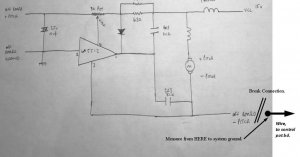
When I look at your drawing, it looks like you are measuring at the motor (-)P pin to ground. If you look at the drawing where I pointed, it is NOT at the motor. It is at the disconnected end of the wire that normally would be attached but is not now for the test.
I'm asking you to break the connection at the motor to the (-) pitch control wire to ISOLATE the motor and that wire because I want to know if there is an inadvertent short to ground somewhere. So if you disconnect (desolder?) the wire at the motor, and check it against ground (the wire, not the motor terminals). What do you get?
The thing is this: The motor windings, when reassembled, gets it's ground THROUGH the IC. If you are measuring at the motor (assembled) pin, then you are checking for resistance to ground through the IC. 496 is fine but I am curious to know if there is an alternate path to ground outside of the motor and that's why I'm asking you to break the connection and check for resistance to ground in that manner.
Ok Norm, sorry I misunderstood.
Tested the resistance from both the end of the pitch control board lead -pitch pin AND from the -pitch point on the pitch control pcb, to the same ground on the main pcb and am reading OL at both.
I think since it is showing OL from that point that it will be the same from the wire at the motor -pitch lead when desoldered but I'll try this too.
Edit: desoldered -pitch wire from motor and tested resistance with same result as above.
Dave, can you recheck & verify your drawing against the data sheet sample circuit regarding ic pinout assignments? It's not reconciling.
- Status
- Not open for further replies.


