Big Ben deck playback too fast
- Thread starter docs
- Start date
You are using an out of date browser. It may not display this or other websites correctly.
You should upgrade or use an alternative browser.
You should upgrade or use an alternative browser.
- Status
- Not open for further replies.
Bit if a weird thing happened.
I tried a 1watt 47ohm resistor without replacing the chip yet and the deck now diesn't seem to have the strength to activate. The motor kinda works but doesn't have the powerrrrr captain. I'm hoping that the chip will be the last remaining problem.
In readiness, I've removed the 1 watt resistor to place the right one in with the chip when they arrive.
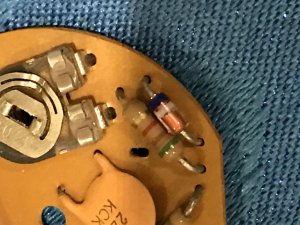
Were you able to find a datasheet on that controller? Now might be a good time to compare and verify the components. You are sure that's a resistor and not a fuse or something right? And that diode, is that a standard or zener?
No, I could'nt find an internal datasheet for the IC.
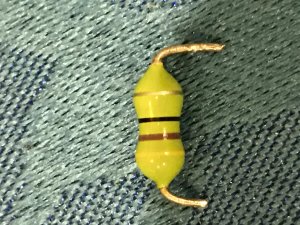
I guess the green resistor could be fusible but I couldn't say one way or another for certain.It does have the usual colour bands on it which read 47ohm.
The diode and other resistors I've checked and they all check out. Again not sure about the diode being a zener or not.
I guess the green resistor could be fusible but I couldn't say one way or another for certain.It does have the usual colour bands on it which read 47ohm.
The diode and other resistors I've checked and they all check out. Again not sure about the diode being a zener or not.
caution
Member (SA)
Yeah, if the marking begins with a D that's a good sign - these can be surge arresters, spark gaps, thermistors, all kinds of things, so it can take some sleuthing. The only thing I can find for a two-band diode is this old Panasonic, but it's violet and white, and yours looks blue and white. One two-band diode I found that was green and blue ended up being a 56V zener, but that's not always what two bands mean. Yours would be either 49V or 69V if that was true.
Bands can mean polarity, value, kind of diode or nothing at all other than just identifying it as a specific model.

About 2/3 the way down on this page are a couple with blue/violet and white stripe
https://www21.atwiki.jp/mcmaster/m/pages/356.html

Bands can mean polarity, value, kind of diode or nothing at all other than just identifying it as a specific model.

About 2/3 the way down on this page are a couple with blue/violet and white stripe
https://www21.atwiki.jp/mcmaster/m/pages/356.html

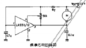
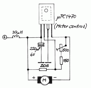
On second thought, and after reviewing a few sample motor speed circuits with various motor speed control IC's, I don't think the circuit has any place for a zener diode, it's probably just a flyback diode so you would test it the same way as a regular diode. Obviously, you would have to test a zener diode differently and map it to determine if it's working properly, and even then, you would need to know the specs before you can know unless you can identify it somehow.
The mysterious green device is probably a resistor although if it's green like that, it's probably a flameproof one or something. Now that I think about it, it seems that at approx 12v, a 47R resistor will allow approximately 250mA current flow @12 and some amount over 300mA @ 15v. I suppose that's about what you might want to limit current consumption at to the motor so perhaps it's a series current limiting resistor. If it failed short, it obviously wasn't limiting current which might've caused the controller to burn out or becomes damaged. Most cases, I see resistors fail by increasing in value, don't see them short as often though. As it appears that you were able to order a replacement IC, I say let's just count your blessings that they are still available and just wait for the replacement before tinkering more.
Here are some sample circuit diagrams I found online.
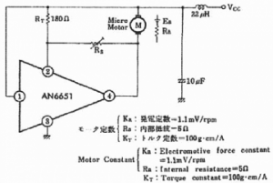


BoomboxLover48
Boomus Fidelis
Replaced the IC and the resistor but am sad to say that the deck still lacks power to engage any of the functions properly 
Might be in need of a new motor since I can't see any other reason for functions not engaging without the power form the motor making them activate and making parts move. If I manually turn the fly wheel, the motor begins to function but just doesn't have the pulling power needed.
Might be in need of a new motor since I can't see any other reason for functions not engaging without the power form the motor making them activate and making parts move. If I manually turn the fly wheel, the motor begins to function but just doesn't have the pulling power needed.
baddboybill
Boomus Fidelis
I thought motor was running fast in beginning? Since you have it opened maybe you should check innards of motor to clean.docs said:Replaced the IC and the resistor but am sad to say that the deck still lacks power to engage any of the functions properly
Might be in need of a new motor since I can't see any other reason for functions not engaging without the power form the motor making them activate and making parts move. If I manually turn the fly wheel, the motor begins to function but just doesn't have the pulling power needed.
BoomboxLover48
Boomus Fidelis
At this stage we have replaced all the internal components of the motor right?
Just curious to know about the voltage on the motor leads.
Can we not now try turning the motor speed adjustment?
RPM is good, but lacks torque?
Just curious to know about the voltage on the motor leads.
Can we not now try turning the motor speed adjustment?
RPM is good, but lacks torque?
That's what I thought which is what made me wonder whether resistor might be fuse or something. Dave, with motor hooked up without the belts, does the speed controls have any effect? Both the internal and external pots. Is there a chance that the internal pot is turned way down in previous attempt to throttle the runaway motor speed? Also maybe try incrementally lowering the resistor value and see if it helps? In fact, maybe even put that old "resistor" back and check if motor control pots are effective again?baddboybill said:I thought motor was running fast in beginning? Since you have it opened maybe you should check innards of motor to clean.Replaced the IC and the resistor but am sad to say that the deck still lacks power to engage any of the functions properly
BoomboxLover48
Boomus Fidelis
In that case include a variable pot to replace that resistor- say like 5 K over that range and see what it can do to fine tune the speed.
May be we can now bring it down to the right speed.
It is a bit tricky to fish the wires out and connect that pot externally out from of the motor assembly (another external speed control pot).
I am so much inclined to see how that green resistance value affects the speed.
What do I know!
Norm will have better suggestions.
BoomboxLover48
Boomus Fidelis
Ghettoboom767 said:This is so informative and I don't own a Big Ben!


Increase the value of it with a variable pot....see how that respond...docs said:Inerestingly, the pot on the board doesn't seem to do anything either.
A choke makes more sense but I would've thought it would have more than 1ohm. And so did you test that internal pot? I was under impression that you tested all the components. I also see another more conventional looking inductor already.
- Status
- Not open for further replies.


