I traced the same board and see some issues. Since the power and alarm buttons each have two rows of six pins, I assume that they're 4-gang SPDT switches. Each row should have two switches, with each common pin the second pin in from each end of the row of pins (the second and fifth pin).
If correct, the PCB does not match the schematic. One of the rows of pins for the alarm button has nothing connected to the last two pins, which would mean nothing is connected to one of the common pins of a switch, even though all four switch sections for the security button are on the schematic: S2002-1, S2002-2, S2002-3 and S2002-4.
Also, I see PCB connections to all four switches for the power button, but only see switches 1 and 2 on the schematic. S2001-3 and S2001-4 are missing. It's possible the engineers connected to some pins as a way to get a PCB trace past a pin blocking its destination, and knew that connecting to the other pin didn't affect the circuit. I've seen that before in old audio gear. So even though these switch sections have connections to some of their pins, they don't actually do anything useful and were left off of the schematic.
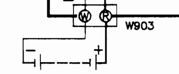
Since I have photos of the transformer board, I know where the wires going to the power switch board are supposed to go, and not only are the names for the two switches for the power light backwards (S2001-1 and S2002-1) but there is no consistency to the layout of the four switches in each button. The section-1 switch for each button seems to be in the far outer corners for each switch, putting them on opposite rows from one another. The pin ordering is also inconsistent, because if the common pin of one of them ties to a throw pin on the other, then why does the board have a trace connecting the second-to-last (common) pin together across switches in each button?
Anyway, I don't have pics of where all the other wires go on the amp and tape deck boards, so I can't figure out how the four switches in each button are arranged, if their ordering is different between the two buttons, and if my assumption about the ordering of common and throw pins is right.
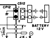
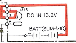
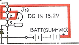
Oh by the way, in those diagrams I posted of the batteries/AC/DC configurations, I noticed a mistake. The schematic we all have for this unit came from the back of a Clairtone 7980 user manual. That version has reversed polarity on the DC jack from the Conion version. The C-100F has ground on the center pin and power on the outside, and the 7980 has power on the center pin and ground on the outside. But when you look at the schematic, the center pin (CN802 pin 5) has a little vertical line connecting it down to the ground line running under it. Clairtone didn't finish modifying the Conion schematic when redrawing it for the reversed polarity. That connection should not be there. The only thing the center pin should connect to is D805.