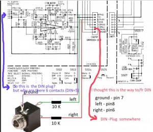
Ah, now I see. With your first reply I did not understand because I thought my variation was just the same as yours. But what you added in the meantime about bypassing made clear that it is absolutely not the same. You see, I am not a specialist in reading schematics. My fault was, that I thought that the way of the signal from the DIN would be the same as the way from your new 3.5 jack. The reason for my mistake was that I just did not see the DIN plug anywhere in this schematics. I think I have found it now. I actually thought that it is the location shown below before, but I thought it was not this one,because there are 6 contacts and the DIN socket has only 5. Why is that? Am I right with the location of the DIN socket? See Pic:goodman said:My Idea is to bypassing the phono amp.
In this case, you must open the radio, drill hole for 3.5mm jack,
find 8 pin connector, with a soldering gun making electrical connections.
RC-MJ70 Line In DIN question
- Thread starter EX_m71_Owner
- Start date
You are using an out of date browser. It may not display this or other websites correctly.
You should upgrade or use an alternative browser.
You should upgrade or use an alternative browser.
- Status
- Not open for further replies.
Thank you Caution , even though I do real changes in the unit, they are only inside and can not be seen (without switch). And the times when I needed to really connect to a turntable for recording are long gone. The phono line is probably not used by many people generally .caution said:I noticed that the aux input on my C-100F uses the same op amp, but it has a switch that allows you to toggle between line-in and phono on the same RCA jacks.
Instead of just using a 10k in series for line-in, they used a voltage divider setup with a 39K in series with a 6.8K to ground, which is probably a little better. When all positions for switch S102 are toward the op amps, it's in phono mode. When they are positioned away, it connects to the resistor divider networks for line-in mode. The part values are all slightly different but accomplish the same task.
If you don't want to add another jack, you could just convert the phono to be line-in insteadOr add a switch and have both
goodman
Member (SA)
Look carefully next picture.
On the top in purple color is DIN socket.
In blue color is DIN amplifier.
Signal from DIN socket go to DIN amp and go to recording head.
You dont need to do anything here.
In green is chinch for PHONO IN.
In red is PHONO amplifier.
Signal from PHONO chinch go to PHONO amp and conected to MODE SWITCH (3 yellow lines)
My idea is bypasiing Phono amp, and conect 3.5 mm jack to this 3 yellow lines
- this is the 8 pin conector - you need pin 6, 7, 8. (see my previous picture)
When MODE switch is on PHONO position,
signal from 3.5 mm jack go direct to FINAL JVC amplifier.

picture of din and phono plate.
In red is 8 pin connector - you need pin 6, 7, 8.

On the top in purple color is DIN socket.
In blue color is DIN amplifier.
Signal from DIN socket go to DIN amp and go to recording head.
You dont need to do anything here.
In green is chinch for PHONO IN.
In red is PHONO amplifier.
Signal from PHONO chinch go to PHONO amp and conected to MODE SWITCH (3 yellow lines)
My idea is bypasiing Phono amp, and conect 3.5 mm jack to this 3 yellow lines
- this is the 8 pin conector - you need pin 6, 7, 8. (see my previous picture)
When MODE switch is on PHONO position,
signal from 3.5 mm jack go direct to FINAL JVC amplifier.
picture of din and phono plate.
In red is 8 pin connector - you need pin 6, 7, 8.
Thank you Goodman - and Caution
I should have had a closer look at Cautions 2 pictures (or the JW manual resp), but once I had seen the pictures made by Goodman (with the external jack) I only looked at this further. So I did not see the DIN socket of course because it was not on there.
Well , you both will probably think, if I really will do that change, that will turn out in a desaster and my M70 will
  , because I am obviousely not that what you would call an electronic specialist. But when I will be up to it I will have an electronic pro with me. I just wanted to understand as well and by that also learn something . And you helped me a lot - THANK YOU.
I will post, when I will do it. Before I will try to clean contacts of the unit, because I have a lot of problems especially with the SOurce switch. I have to "play" with it again and again everytime I change source until I can hear correct volume and both channels. When this is done I will do start with the modification.
I should have had a closer look at Cautions 2 pictures (or the JW manual resp), but once I had seen the pictures made by Goodman (with the external jack) I only looked at this further. So I did not see the DIN socket of course because it was not on there.
Well , you both will probably think, if I really will do that change, that will turn out in a desaster
and my M70 will , because I am obviousely not that what you would call an electronic specialist. But when I will be up to it I will have an electronic pro with me. I just wanted to understand as well and by that also learn something . And you helped me a lot - THANK YOU.I will post, when I will do it. Before I will try to clean contacts of the unit, because I have a lot of problems especially with the SOurce switch. I have to "play" with it again and again everytime I change source until I can hear correct volume and both channels. When this is done I will do start with the modification.
goodman
Member (SA)
Thanks for the kind words. I'm glad that I helped you.
I waiting for information and photos of the modification process.
PS:
I think, that you won't use phono and din connectors,
and won't make modification on phono board.
In this case, must disconnect 8 pin jack from phono board.
This is easy way to stop 12 v to phono amp (pin 5).
This is important step!!!
Connect 3.5 mm jack with resistors to this 8 pin connector. You need pin 6, 7, 8.
I agree with member caution about resistors. 10 kohm is min. value.
Adjust of sound level depends of type music, mp3 player volume, and this resistors.
You must test first with 33 k ohm, and low volume of MP3 player.
If sound level is low you can use 20 K ohms or 10 K ohms.
goodman
Member (SA)

Find a 8 pin jack.
Solder violet cable to ground (7).
Cut the cables for L (8) and R (6) channels at 4-5 cm before jack.
Solder 8a to 3 (L channel).
Solder 8b to 1 (L channel).
Solder 6a to 4 (R Channel).
Solder 6b to 2 (R Channel).
PHONO IN - work as before modification.
LINE IN - use 3.5 mm jack for line in, phono input is disconnected.
BT module line out must be connect to 3.5 mm line in jack.
You need power supply to BT module too.
This is on theory.
I don't have this box to made this mod.
Dancorp
Member (SA)
Where's Wally?
https://photos.app.goo.gl/wooGZBz1Zvyfakcu1
The easiest way would be to have the M70L service manual..
Someone to share it pls ?
https://photos.app.goo.gl/wooGZBz1Zvyfakcu1
The easiest way would be to have the M70L service manual..
Someone to share it pls ?
trippy1313
Member (SA)
caution
Member (SA)
CN571 is hard to get at. If you don't feel like disassembling to access it, you could follow the connector wires and solder to the other ends, on the main board.
You can barely see pin 1 at the bottom end, just like the way it's oriented in the schematic image in comment #28.

You can barely see pin 1 at the bottom end, just like the way it's oriented in the schematic image in comment #28.
Dancorp
Member (SA)
Thanks a lot Caution, i'll try to follow the connector.
fyi, i bought the service manual, but i can't upload it to the JVC section... why ?
https://drive.google.com/open?id=1RaGlZE9AILnmJ7qKRr50hz6hxG1ohzMT
fyi, i bought the service manual, but i can't upload it to the JVC section... why ?
https://drive.google.com/open?id=1RaGlZE9AILnmJ7qKRr50hz6hxG1ohzMT
trippy1313
Member (SA)
If it's one of SuperDuper's manuals from Analog-alley, might be a copyright thing or whatever it's called.Dancorp said:Thanks a lot Caution, i'll try to follow the connector.
fyi, i bought the service manual, but i can't upload it to the JVC section... why ?
https://drive.google.com/open?id=1RaGlZE9AILnmJ7qKRr50hz6hxG1ohzMT
Dancorp
Member (SA)
By following wires from connector, i located the 2 positions on the main board. (that's close to the source switch)
i just soldered my bluetooth board on them with 16K resistors.
That works fine !
https://photos.app.goo.gl/vQulYI3Jkht6ju2f1
Maybe it wiould not be recommanded to do that without cut the connection with the phono amp ?
(sorry for my english)
i just soldered my bluetooth board on them with 16K resistors.
That works fine !
https://photos.app.goo.gl/vQulYI3Jkht6ju2f1
Maybe it wiould not be recommanded to do that without cut the connection with the phono amp ?
(sorry for my english)
caution
Member (SA)
Look carefully at the image in comment #28. Notice how he erased the connection between 6a/6b and 8a/8b? He shows you how to cut the connection to the phono amp and run the phono amp output (6a and 6b) to one side of a switch, and the line in jack you added to the other side of the switch. 8a and 8b are the common lines, going to the function switch. They should be on the common pins of the phono/line switch.

- Status
- Not open for further replies.