Below is a description of the repair process for my M90 deck. By no means will this be the "Fix All" for every deck, but you should be able to follow these instructions to at least check these problems off your list.
A HUGE shout out to Boomboxery member DOCS for walking me through this process at great cost to his time. I can't thank him enough.
To start with, your going to need the M90 service manual available at http://www.analogalley.com/. This is a tiny investment that will pay for it's self once you have a fully working M90 should you ever choose to sell your radio.
My radio's symptoms:
Line in and Radio were fully functional. The deck was completely dead with a cassette stuck inside. When pushing the power button, an audible CLUNK was heard. None of the buttons, FFW, REW or Play worked. The music search lights did come on, but nothing happened with the deck.
I was able to locate two distinct problems with my deck that I think are common problems, one that may have led to the other and caused the failure.
Repair Part 1:
Remove the back of the radio (without it being plugged in!)
Remove 5 purple screws that hold the deck in the back of the unit (4 short, one long)
Unplug all the connections going to the deck. There will be a series of grey wires that can not be unplugged. This is not an issue, leave them connected, they are long enough to pull the deck from the radio and service it.
Re-belt if needed (recommended). Belt info here. There is nothing tricky here, 3 belts, easy to get to.
In the JVC service manual "Supplementary" section, on page 2 you will find the "Mechanical Control P.W.B. Parts" diagram and on page 3 you will find the parts list.
The components you are looking for are FR701, FR702, FR703 and FR704. These are "Fusible Resistors". They are designed to "Pop" like a fuse to prevent damage to other components. This is a common point of failure on this radio and built into it's design.
Remove the 4 small screws that hold the PC board to the back of the deck mechanism. Be careful with all these components.
Using a multi meter, you want to check the values of component FR701, FR702, FR703 and FR704. These are OHM measurements. The location of these fusible resistors are in the diagram on page 2 of the service manual.
IN MY CASE I was able to locate FR704 as being burnt. It tested DEAD on the multi meter and was visually "cooked" and dark in color compared to the other 3 fusible resistors.
This is the fusible resistor that was burned on mine.
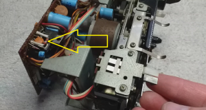
NOTE: the four fusible resistors are different values. two are 4.7ohms, one is 10 and the other is 2.2.
I chose to replace ALL FOUR fusible resistors with new ones. I bought them from https://cpc.farnell.com/ They were CHEAP! I bought extra's, 10 of each, it was £5.76 (in British Pounds) delivered (in the UK).
One at a time, I un-soldered, removed and tested each fusible resistor. Confirming the one that was burnt and the values of the 3 I was replacing to make sure they matched what I was putting back in with the new ones I bought. Once confirmed, I reinstalled. This was very easy.
Repair Part 2:
Once the fusible resistors were installed I found a small component laying on my work bench under the deck. This small component was part of a leaf switch assembly that I believe was the ACTUAL problem with the deck that caused the fusible resistor to blow.
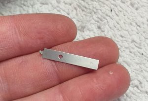
This piece is part of the lever switch that tells the deck if there is a cassette in the carriage tray (white). It is located right next to the switch that tells the deck if the tape that is inserted can be recorded on (black).
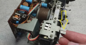
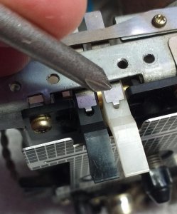
In my case, the metal part of the switch became detached from the plastic part (white). This meant that when the cassette was inserted in the deck, the switch was not pushed, letting the deck know there was a cassette in the tray. It is this reason that I believe the fusible resistor may have blown (hypothetical). Testing this switch with a multi meter would be a good isea, even if your switch is not broken. Test with out a cassette in the tray and then with one in the tray and see if the switch is working.
In my case, this little button that holds the metal part to the plastic part popped off.
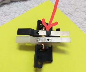
The metal part is under pressure when engaged and will not hold with glue.
I modified a micro machine screw to re-attach the two pieces.
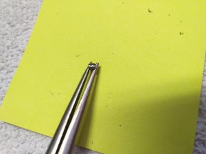
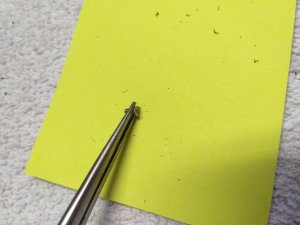
I then hand drilled out the original plastic holder shaft.
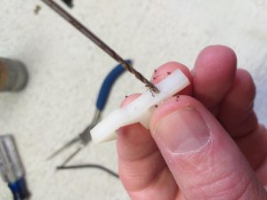
I then put the screw in place to hold the parts together
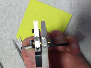
It is important that the "Button Head" of the screw be the same thickness of the "Button head" of the plastic piece on the other switch. This was 0.45mm. I used a dremil to grind the screw head to the correct thickness. I then cut a slot in the head of the screw for a screw driver.
Everything was then reassembled. The switch should be level with the switch next to it and operate freely.
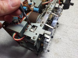
I reassembled everything and the deck worked the first time.
Hopefully this will help other get their M90 decks working. Good luck.
A HUGE shout out to Boomboxery member DOCS for walking me through this process at great cost to his time. I can't thank him enough.
To start with, your going to need the M90 service manual available at http://www.analogalley.com/. This is a tiny investment that will pay for it's self once you have a fully working M90 should you ever choose to sell your radio.
My radio's symptoms:
Line in and Radio were fully functional. The deck was completely dead with a cassette stuck inside. When pushing the power button, an audible CLUNK was heard. None of the buttons, FFW, REW or Play worked. The music search lights did come on, but nothing happened with the deck.
I was able to locate two distinct problems with my deck that I think are common problems, one that may have led to the other and caused the failure.
Repair Part 1:
Remove the back of the radio (without it being plugged in!)
Remove 5 purple screws that hold the deck in the back of the unit (4 short, one long)
Unplug all the connections going to the deck. There will be a series of grey wires that can not be unplugged. This is not an issue, leave them connected, they are long enough to pull the deck from the radio and service it.
Re-belt if needed (recommended). Belt info here. There is nothing tricky here, 3 belts, easy to get to.
In the JVC service manual "Supplementary" section, on page 2 you will find the "Mechanical Control P.W.B. Parts" diagram and on page 3 you will find the parts list.
The components you are looking for are FR701, FR702, FR703 and FR704. These are "Fusible Resistors". They are designed to "Pop" like a fuse to prevent damage to other components. This is a common point of failure on this radio and built into it's design.
Remove the 4 small screws that hold the PC board to the back of the deck mechanism. Be careful with all these components.
Using a multi meter, you want to check the values of component FR701, FR702, FR703 and FR704. These are OHM measurements. The location of these fusible resistors are in the diagram on page 2 of the service manual.
IN MY CASE I was able to locate FR704 as being burnt. It tested DEAD on the multi meter and was visually "cooked" and dark in color compared to the other 3 fusible resistors.
This is the fusible resistor that was burned on mine.

NOTE: the four fusible resistors are different values. two are 4.7ohms, one is 10 and the other is 2.2.
I chose to replace ALL FOUR fusible resistors with new ones. I bought them from https://cpc.farnell.com/ They were CHEAP! I bought extra's, 10 of each, it was £5.76 (in British Pounds) delivered (in the UK).
One at a time, I un-soldered, removed and tested each fusible resistor. Confirming the one that was burnt and the values of the 3 I was replacing to make sure they matched what I was putting back in with the new ones I bought. Once confirmed, I reinstalled. This was very easy.
Repair Part 2:
Once the fusible resistors were installed I found a small component laying on my work bench under the deck. This small component was part of a leaf switch assembly that I believe was the ACTUAL problem with the deck that caused the fusible resistor to blow.

This piece is part of the lever switch that tells the deck if there is a cassette in the carriage tray (white). It is located right next to the switch that tells the deck if the tape that is inserted can be recorded on (black).


In my case, the metal part of the switch became detached from the plastic part (white). This meant that when the cassette was inserted in the deck, the switch was not pushed, letting the deck know there was a cassette in the tray. It is this reason that I believe the fusible resistor may have blown (hypothetical). Testing this switch with a multi meter would be a good isea, even if your switch is not broken. Test with out a cassette in the tray and then with one in the tray and see if the switch is working.
In my case, this little button that holds the metal part to the plastic part popped off.

The metal part is under pressure when engaged and will not hold with glue.
I modified a micro machine screw to re-attach the two pieces.


I then hand drilled out the original plastic holder shaft.

I then put the screw in place to hold the parts together

It is important that the "Button Head" of the screw be the same thickness of the "Button head" of the plastic piece on the other switch. This was 0.45mm. I used a dremil to grind the screw head to the correct thickness. I then cut a slot in the head of the screw for a screw driver.
Everything was then reassembled. The switch should be level with the switch next to it and operate freely.

I reassembled everything and the deck worked the first time.
Hopefully this will help other get their M90 decks working. Good luck.


