JVC RC-M70JW - Left volume slider always on MAX volume once it's 1/2 way up, right slider works perfect

Tinkererman

Member (SA)
Hi Guys,

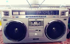
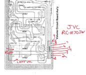
I picked up a nice clean JVC RC-M70JW recently, every slider works perfect except one, the LEFT Volume control.

The Left slider doesn't respond at all, no sound at all until you hit the half way mark and then BAM, it is on MAX volume as it will not get any louder as I push it up towards the MAX, it stays the same, FULL BLAST, but if you back it down just a hair, it has ZERO left channel volume.
I've never had a slider do this type of thing, kind of strange.

So when it does that, I move the right slider up to match the left channel volume level, and indeed it is on Max Volume.

The right slider volume works perfect through it's entire travel range from minimum to maximum as it should.

All other sliders work great, Bass and Treble respond well through their ranges etc., I have yet to clean any of them as I just got this.

Looking for thoughts on this issue as I have never even heard of it, so the left channel slider is either full bore volume or no volume.
As soon as the slider hits the mid-point in it's travel, it's on MAX, but no volume at all until you hit that mid-point in it's travel.

Thoughts? Shorted out? Cracked board, weird for sure. I've had a bunch of these apart in the past, so I'm not afraid to dive in deep.

I thought maybe someone has run into this issue at least once??

Thank you all for any and all replies, Rich
 

Tinkererman

Member (SA)
It's a really clean unit also, must have been stored in a clean dry place for decades.
 

Attachments

  • 0503261158.jpg
    0503261158.jpg
    150.5 KB · Views: 15

Superduper

Moderator
Staff member
The internal slider feeler contacts have detached internally from the main nylon slide block. New parts are no longer available. You will have to rebuild that slider by disassembling it, reaffixing the loose or detached contact. If you continue to operate the slider, you risk damaging or mangling that part where it is beyond repair since it's either going to get crushed by the nylon block, or it will get dragged and scratch or grind off the carbon on the resistor board. Search the archives for additional threads about this issue, it's a common issue.
 

XLVII

Member (SA)
Hi. Does the left channel exhibit same tendencies when using headphone jack? Assuming you tried spritz of deoxit (f5). More details such as: issue occurs regardless of source; tried with batteries, etc.
 
  • Like
Reactions: Tinkererman

XLVII

Member (SA)
Looks like you got your answer. I'm always searching Ebay and have (2) of each model boombox in collection. Quite often this is the only way to acquire parts. Good Luck.
 
  • Like
Reactions: Tinkererman

Tinkererman

Member (SA)
Thanks much Superduper, and XLVII,

I'll have it apart soon, I'm going through some health issues and have some tests this week.

Slider feels prefect, no grinding, nothing - so I won't mess with it until it's off the board and apart.

Never had one that exhibited that exact problem, Rich
 

Tinkererman

Member (SA)
Hi Guys,

It must be this damn Lyme disease I've had for 19.5 years - BUT can someone PLEASE Let me know if PIN 1 and 2 are the correct 2 pins to check the resistance of the LEFT Volume slider, and PINS 3 & 4 for the RIGHT volume slider. The right side worked perfect, just the left had the issue I described above.

They are 50K B Curve sliders, right? I will check for cracked solder joints to in a bit.

This box is so mint inside, not even any dust, and I looked inside the left slider in question and it looks "cherry"

I'm just not having a good day, I had a cancer scare the last few months, came back negative last week, but still having health issues.
I think the Lyme is coming back strong and I have 5 lesions in my brain already as of 2006.

Thanks, Rich
 

Attachments

  • board.jpg
    board.jpg
    255.9 KB · Views: 10
  • JVC RC M70JW tone board.jpeg
    JVC RC M70JW tone board.jpeg
    214.8 KB · Views: 11

caution

Member (SA)
You need to look at the schematic to see how the pin numbers associate with the volume pot.

Pin 1 is one end of the volume pots. Both are grounded, so they share the same pin (5) at connector CN561. (green line)
Pin 2 is the wiper. CN561 pin 1 for the Left channel, and CN561 pin 3 for the Right channel (pink line)
Pin 3 is the other end of the volume pots. CN561 pin 2 for the Left channel, and CN561 pin 4 for the Right channel. (blue line)
Pin 4 is the center tap for the loudness circuit

The schematic doesn't show two copies of the circuit for left and right - only the left side. The right channel's nodes are truncated with little arrows.

1778440061044.png
 

Tinkererman

Member (SA)
I tried multiple ways but can't get a 1 to 50K ohm reading on either slider, probably because there's other resistors in the circuit.

I'll take it off the board and check it out soon.

Thanks, Rich
 

Tinkererman

Member (SA)
Ok, I took the pot off the board, and it goes open circuit around 25K ohms.

The break in the carbon track looks like it was designed like that, but I guess it could have just been poor manufacturing?

The feelers look good to me and there was no crud inside it either.


Can you guys confirm it's just the break in the carbon track almost dead center?

0511261856b.jpg0511261858a.jpg0511261900.jpg
0511261857c.jpg
 
Last edited:

Transistorized

Member (SA)
That break seems to be in most all photos I've seen. I think it has something to do with the center tap for the loudness control. Here's another photo of the volume from another post about the alps sliders

pxl_20220707_073418657-jpg.55176


The photo above was from this post here.
 
  • Like
Reactions: Tinkererman

Tinkererman

Member (SA)
OK, Thanks very much Transistorized,

I have some sliders here that are 45mm total length, and 30mm travel, but they are A100K I believe, and they won't fit the holes properly. I'll look around, but I know these are "Unobtainium" basically.

So, there's no way to repair that track I assume, and the ohm value would be off anyway at the break if I used like rear window defroster grid repair.

What I don't understand is why I had ZERO volume up until I hit the break, because I did have variable resistance up to that point, then it went and stayed at 100% volume all the way to the end of it's travel with an "open" circuit, but I am not trained in Electronics, so I imagine I wouldn't understand it either way.

On the hunt I guess.... Thanks all, Rich
 

caution

Member (SA)
That is correct - the point of the center tap is so the loudness EQ filter circuit cuts out for the upper half of the volume setting. Low volume audio is inherently starved of low frequencies.

As you turn the volume up from 0% to 50%, the loudness circuit gradually tapers off, so by the time you hit 50%, that filtering is gone for the rest (50%-100%) of the way. You only need bass boost for 0-50% volume setting.
 
  • Like
Reactions: Transistorized

Superduper

Moderator
Staff member
If you want to test to see if the carbon track is actually fractured, simply place one lead of your meter on one of the rivets, and then drag the other test lead across the carbon strip. If you see rising (or dropping) resistance, and suddenly O/C, then you've found your fracture. It should read continuity across the entire range of the carbon strip. This only tests if your carbon strip is still serviceable. Hopefully yes, and if so, then the issue is either that your contacts need cleaning, or the feelers are excessively loose on the nylon block. Also, I'm not sure what all that stuff is on your nylon block is, every one I ever see is perfectly smooth, and I've seen a lot. Yours looks like they were buttered with lard or mayonaise.
 

Tinkererman

Member (SA)
If you want to test to see if the carbon track is actually fractured, simply place one lead of your meter on one of the rivets, and then drag the other test lead across the carbon strip. If you see rising (or dropping) resistance, and suddenly O/C, then you've found your fracture. It should read continuity across the entire range of the carbon strip. This only tests if your carbon strip is still serviceable. Hopefully yes, and if so, then the issue is either that your contacts need cleaning, or the feelers are excessively loose on the nylon block. Also, I'm not sure what all that stuff is on your nylon block is, every one I ever see is perfectly smooth, and I've seen a lot. Yours looks like they were buttered with lard or mayonaise.
Hi Superduper,

The "lard or mayonnaise" you describe must be the original grease they used in the production, maybe??

I can tell this box was stored for ages, and never opened up, every little plastic zip tie was intact, and I think this one slider must have broken during it's very early years and then shelved for decades, at least it was stored in a good environment, everything looks pretty much spotless inside.

The carbon strip on my broken slider goes open circuit at about 25K ohms, half way through it's travel, like "caution" said I guess right near the center loudness tap is a common spot, and once you get past the break and back onto the carbon track, it's still open circuit, I assume that is normal once there's a break in the track.

I am looking around here, but all I have are these NOS "A100K" sliders. I think I have 15 of them. They are the same size 45mm long, 30mm travel, the aluminum body is slightly thinner in depth though and they won't work because I need 50K anyway and they mount to the board in a different manner. See the attached images of the new ones I have.

So, I guess I need a new carbon track for this one, or possibly fix the carbon track, but I would rather have a perfect carbon track, a not a repaired one with rear window defroster repair or similar. The "feelers" look very good to me, I don't see any cracks in the nylon block at all and the contact points look excellent under a jewelers loupe.

Thanks, Rich0512261050b.jpg0512261101b.jpg0512261102b.jpg
 

Superduper

Moderator
Staff member
You won't find the perfect replacement, many have looked. Either the pins are wrong, or the curve is wrong, or the mounted height is wrong, or the knob shaft is wrong.... Also, if you have mismatched left and right sliders, even if physically everything else is perfect, there will probably be slight differences in curve characteristics. Meaning you might have one control at the 4 position, but the other will be at 2.5, or 6 to match the same volume level. Also does the replacement also have a center loudness tap? Because without it, your left and right channels will sound different.

A far better option is to just repair your existing one. Get yourself some conductive epoxy, they are used specifically to repair broken circuit board traces. Identify the exact spot of the fracture with your meter (and microscope if you have). Apply just a tiny amount to bridge that break, NO MORE or you'll chance the resistor characteristics. Be aware if you go this path, you should get the true epoxy, not the heat cured version, unless you decide to bake it afterwards. If you don't cure it properly (either with catalyst or heat), the epoxy will never fully cure hard.

Also did you measure resistance from rivet to rivet? If O/C then that confirms that carbon fracture. If you are getting resistance, the track isn't broken.
 

Superduper

Moderator
Staff member
I've fixed several over the decades, and each time, the offerings change. The best product I've used with great success is MG Chemicals 8331D. See description here:

However, what used to be $15 is now like 10x more expensive, and you can consider it pretty much like a 1-time use product because it has such a short shelf life. There are cheap alternative products but those are most all pretty much 1-part epoxy which means there's no catalyst to mix together. This means it's pretty much just a glue and not an epoxy, but follow the directions carefully. Many that says epoxy is actually a heat cure product which I highly recommend you do. Bake it in your toaster oven after it has come up to temperature. Many of those heat cure products aren't actually conductive until it has cured. Only apply as much as it takes to bridge the fracture, no more. Because unlike the carbon track which has a high resistance per mm of length, these have very low resistance comparatively speaking, and applying too much will alter the resistive characteristics. The real MG stuff is the best as it cures hard and abrades well. But I understand the cost issue. Also, while you are at it, I generally like to add a glob at the rivets. Those fracture all the time so since you have the product and it probably will expire anyways before your next use, if ever, might as well add it now.

I've used one type of heat cured epoxy on my last repair and it did work ok, but since I don't recall the brand, I won't recommend any at all, you'll just have to try it yourself, unless you are willing to pony up for the MG stuff.