JVC M90 Deck issues

mark

Member (SA)
Hello guys
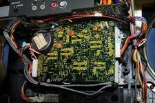
Managed to get most of the issues with my M90. Now it’s time to fix the deck.
Currently the motor spins constantly.
No other life or capability is present.
Solenoid works when jumped and the deck will manually operate through its head lifting and lowering function.

What are the list of common deck issues?
Items to replace? Capacitors, transistors…
 

Attachments

  • IMG_8394.jpeg
    IMG_8394.jpeg
    38 KB · Views: 16

mark

Member (SA)
Ok I’m in!!
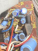
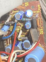
Do these FR 703, FR704…. Look fried?
 

Attachments

  • IMG_8434.jpeg
    IMG_8434.jpeg
    154.3 KB · Views: 9
  • IMG_8432.jpeg
    IMG_8432.jpeg
    230.1 KB · Views: 13

mark

Member (SA)
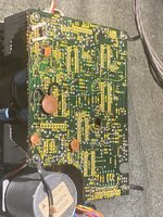
I’m thinking these FR’s are fried….
FR101, FR102, FR103 and FR104.
 

Attachments

  • IMG_8435.jpeg
    IMG_8435.jpeg
    93.2 KB · Views: 11
  • IMG_8434.jpeg
    IMG_8434.jpeg
    154.3 KB · Views: 12
  • Like
Reactions: Tinman

Superduper

Moderator
Staff member
As fusible resistors go, those don’t look too bad as most fried ones literally looked toasted. By their very nature, fusible resistors run very hot which is why they are elevated (to prevent scorching the pcb) and have those special flameproof sleeves on the leads. However I’m not sure why you are visually analyzing them, just take a multimeter and measure their resistance, then you’ll know in 60 seconds. Given their age, they might not be shorted but I’ll bet their values have drifted.
 

Tinman

Member (SA)
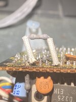
704 (on the back of the board) looks like it could be cooked.
That's the one that usually causes the running motor.
These are normally gray colored so don't go by that.
 

Superduper

Moderator
Staff member
704 (on the back of the board) looks like it could be cooked.
That's the one that usually causes the running motor.
These are normally gray colored so don't go by that.
Again…. Just TEST it. Everyone that can break down a piece of gear to that extent and is contemplating replacing components has (or should have) a meter, and know how to use it. In fact, in 1/10th if the time that it takes to snap photos, upload the pics and post a question, the answer would have already been clear. No deep thoughts mulling over a resistors appearance, no guessing, just answers.
 
  • Like
Reactions: Tinman

Hajidub

Member (SA)
Motor running constantly? PB motor, capstan motor? Could be as simple as cleaning the reed switches. The fuse resistors look solid to me, but we need more info.
 

Tinman

Member (SA)
Again…. Just TEST it. Everyone that can break down a piece of gear to that extent and is contemplating replacing components has (or should have) a meter, and know how to use it. In fact, in 1/10th if the time that it takes to snap photos, upload the pics and post a question, the answer would have already been clear. No deep thoughts mulling over a resistors appearance, no guessing, just answers.
I just pointed out that 704 looks like it could be burnt and never said it was definitely the problem.
Obviously the only way to know for sure is to test them.
It seemed to me that he thought they're all bad or "fried" because they're gray.
Whether or not he can test them is beyond me.
 

Superduper

Moderator
Staff member
I just pointed out that 704 looks like it could be burnt and never said it was definitely the problem.
Obviously the only way to know for sure is to test them.
It seemed to me that he thought they're all bad or "fried" because they're gray.
Whether or not he can test them is beyond me.
I might have come across as a bit harsh. But that wasn't the intention. Over the years, there's been too many folks showing photos of PCBs and asking, "what's wrong". In my experience, I've come across components that looked mint but which tested short or open. I've seen stuff that looked horrible, but tested in spec. The point is that we simply can't tell by a visual examination to conclude whether something needs replacement or not. There is no visual measure by which we can judge definitively whether something is causing a particular symptom. Ok, as usual, there's always an exeption to the rule, because I've also seen components with clear visual damage (like IC's and power transistors with holes in them and scorching that looks like someone took a blow torch to them.) Needless to say, I'm not talking about those as those are obvious.

In this case, the fusible resistors in the M90 deck are known points of failure. There simply is no reason to attempt to judge the electrical condition of those 4 or 5 resistors by their appearance. They have long leads and stood off from the PCB so they are easy to check. Anyone who can break down a boombox to extract the cassette deck from an M90, contemplate replacing these fusible resistors and have the necessary tools to do so (soldering iron, solder sucker or desoldering braid, etc) must have a multimeter in his possession right? I mean, a multimeter is probably a far more common tool by a factor of 10 I'm guessing, than a good electronics soldering iron. And if a multimeter is not available, then that should be the first tool to get before opening up one of these TOTL boomboxes, no?

Bottom line, it literally takes only a minute or two to test these 4 resistors and then the truth will be known. No guessing. No contemplating the color, shade, smell or whatever with regards to the resistors, and this was basically my point.
 

Tinman

Member (SA)
Anyone who can break down a boombox to extract the cassette deck from an M90, contemplate replacing these fusible resistors and have the necessary tools to do so (soldering iron, solder sucker or desoldering braid, etc) must have a multimeter in his possession right?
"They" say to never assume anything, it's possible he doesn't.
Hopefully he'll chime back in and inform us what's going on.

I bought my first Craftsman auto ranging meter in the late 90s and don't know how I got along without one until then.
I currently have 3.
 

mark

Member (SA)
Hi guys
Superdude is correct
My next question. Should I remove them to test them? Or can I leave them on the board?
 

caution

Member (SA)
You said that the solenoid works and the deck resets, which means that resistor is good.
Just make sure you don't run it without the flywheel belt, or else it won't be good.
 

Superduper

Moderator
Staff member
All of these resistors are low resistance, and these resistors almost always drifts upward in value until they blow which will then usually result open (open circuit). Generally speaking it is likely fine to test them in circuit and you should expect a reading no higher than the spec. For example, a 10 ohm resistor should never read 118 ohms, in which, it’s bad. However if a 10 ohm resistor is reading 5 ohms, you should lift a leg and test again. The reason is that parallel resistance in a circuit could result in a lower reading, but would never result in an increase in resistance. These are general guidelines and will vary based on the individual circuit, but is a quick test that can provide rapid answers, especially with low resistance resistors.
 

mark

Member (SA)
3 out of the 4 fusible resistors we’re good, their values were perfect.
FR704 was dead ☠️
I’ll replace and get back to you guys.
Currently
The solenoid when JUMPED operates and I can manually raise the heads.
The capstan motor spins constantly
No other operations can be done.