Hello!
A friend of mine got a Grundig MGL1451a from e-bay last year.


Unfortunately, it seems that the device is not really working as it should. Only info I could find is a copy of ebay listing, with only two images. One can see that the device was tested in 1978, and once more in 1986. The components inside are from 1972. There is no other data, manual or service manual to be found. At least, I could not find it. Anyway...
I am feeding the input with 1 kHz, 0.7 - 5 Vpp (sinus wave with 3% THD) from signal generator, but the device shows about 0.3 V, and I can not get it to show actual value. E.g. When I apply 3 Vpp, it shows about 0.8 Veff. (edit.I managed to set the THD within of 10% of the value I got with my oscilloscope.) Using the 1k trimer pot, I can't get any usefull change, although the voltage over the 22uF capacitor gets up to 2V, the voltage for indicator is in range of 10s of mV (see image below, see down, indicator marked "napon").
I hoped to see the that there is a rejection of 1kHz by at least 60dB after exiting first board, as I would place the T-filer right at the connector. But, I can clearly see that the first board always has a 100mV signal on the output.
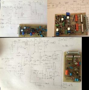
In moment of desperation, I made some drawings of the board that drives both instruments (section down, sorry for some errors), and started to draw the constant-output amp board (top left). There is a image of (presumably) filter board (left).

Could someone give me some advice?
A friend of mine got a Grundig MGL1451a from e-bay last year.


Unfortunately, it seems that the device is not really working as it should. Only info I could find is a copy of ebay listing, with only two images. One can see that the device was tested in 1978, and once more in 1986. The components inside are from 1972. There is no other data, manual or service manual to be found. At least, I could not find it. Anyway...
I am feeding the input with 1 kHz, 0.7 - 5 Vpp (sinus wave with 3% THD) from signal generator, but the device shows about 0.3 V, and I can not get it to show actual value. E.g. When I apply 3 Vpp, it shows about 0.8 Veff. (edit.I managed to set the THD within of 10% of the value I got with my oscilloscope.) Using the 1k trimer pot, I can't get any usefull change, although the voltage over the 22uF capacitor gets up to 2V, the voltage for indicator is in range of 10s of mV (see image below, see down, indicator marked "napon").
I hoped to see the that there is a rejection of 1kHz by at least 60dB after exiting first board, as I would place the T-filer right at the connector. But, I can clearly see that the first board always has a 100mV signal on the output.
In moment of desperation, I made some drawings of the board that drives both instruments (section down, sorry for some errors), and started to draw the constant-output amp board (top left). There is a image of (presumably) filter board (left).

Could someone give me some advice?


