Clairtone 7980 - Tape 1 Mech Question

Endervox

New Member
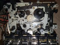
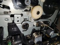
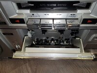
I recently picked up a Clairtone 7980 that someone has tinkered with (I know... it's the worst). Part of it is that I believe the capstan roller assembly has either shifted off the lifting mechanism OR there's a spring missing. Can anyone provide any close up photos of their Tape 1 mech showing how the capstan pinch roller assembly looks?

I also happened to find a spring inside the 7980 case just floating around (assuming it didn't fall out of the JVC MC90C I just finished). Anyone know where this spring may have come from on the 7980?

Lastly, the mechanism is in an engaged position (read tape). It does not disengage when stop is pressed. I'm kind of nervous someone really messed around and damaged the mech. Thoughts?

1768511605231.png
 

caution

Member (SA)
That spring is for that thin pivoting bracket inside the deck door that holds the cassette. There'a a spring like that on each side. They're kind of tricky to insert, you'll probably have to pop out the bracket first.

53853246123_23c40531db_b.jpg
 

Endervox

New Member
That spring is for that thin pivoting bracket inside the deck door that holds the cassette. There'a a spring like that on each side. They're kind of tricky to insert, you'll probably have to pop out the bracket first.
Do you have a pic specifically showing that springs location?

Also, thanks for the photo, can you get one at an angle where I can see if the lip on the capstan bracket (tape side) rests on the mech that moves up and down?

Much much much appreciated!
 

caution

Member (SA)
Sorry bud, I took that picture years and years ago. The unit is no longer open.
Here's where that spring goes
55044495061_44fecaca8f_z.jpg
 

Tinman

Member (SA)
It looks like your pinch roller is disengaged from the torsion spring.
From the two top pics, the spring is the one directly below the capstan shaft.
There's probably an engagement point on the back part of the pinch roller frame.
Pinch rollers typically use torsion or tension springs.
Also, looking at caution's pic, it looks like your pinch roller is missing the retention screw which might be the one in your pic.
I'm just guessing but your pinch roller might be under the mechanism so it could be holding it up in the play position.
 

Endervox

New Member
Sorry bud, I took that picture years and years ago. The unit is no longer open.
Here's where that spring goes
So weird... I can't for the life of me see where the spring would go. I'm going to order belts and wait to dive back in until they arrive.
 

Endervox

New Member
It looks like your pinch roller is disengaged from the torsion spring.
From the two top pics, the spring is the one directly below the capstan shaft.
There's probably an engagement point on the back part of the pinch roller frame.
Pinch rollers typically use torsion or tension springs.
Also, looking at caution's pic, it looks like your pinch roller is missing the retention screw which might be the one in your pic.
I'm just guessing but your pinch roller might be under the mechanism so it could be holding it up in the play position.
Yes. It is definitely under the slider. I am confused by the how the spring could actually attach to the capstan assembly. Some closeups of others mechanisms would be incredibly helpful. Hopefully someone will see this thread.
 

Tinman

Member (SA)
It doesn't attach to the capstan assembly, it attaches to the pinch roller frame.
That torsion spring is mounted on and raises and lowers with the head assembly.
When engaged with the torsion spring like it should be and after you press PLAY, the pinch roller will raise up (with the head assembly) to the capstan shaft putting the correct amount of pressure on it (because of the torsion spring) pulling the tape over the heads at a constant speed.
That's what the job of that torsion spring is, putting the correct pressure between the pinch roller and capstan shaft.
After you press stop or it comes to the end of a tape and it auto stops, the heads along with the pinch roller (because of the torsion spring) drops releasing the tape.
Again, it looks like your pinch roller is missing the retaining screw (possibly the one in your first pic?) and is sitting underneath the head assembly which is why that won't disengage.
I could be wrong because I've never had a 7980 and it's difficult to troubleshoot something through a couple of pics.

Just to verify:
The capstan shaft is the chrome shaft sticking out of the bronze bushing.
The pinch roller is the rubber wheel on the metal frame.
 
  • Like
Reactions: Endervox

Endervox

New Member
So... Few things. I figured out the motor had a bad winding so I bought a new one. Install went good and functionally it works.

THE ISSUE - there's something with the pinch roller assembly. It's sitting too high. I can't even get a tape in there. The lift mechanism that brings the head up seems to be functioning properly, going up and down with a full range of motion. The issue seems to be limited to the roller assembly. I'm wondering if I have it in the wrong spot. The actual wheel is the same size as the factory so I'm confused. Here are a couple of pics. Can someone photograph theirs? I'd really appreciate it!

I'd love to button this thing up... :) I made a 3khz test tape to adjust the speed. I just need to be able to get the tape in!
 

Attachments

  • 20260209_185036.jpg
    20260209_185036.jpg
    224.8 KB · Views: 10
  • 20260209_185058.jpg
    20260209_185058.jpg
    175.5 KB · Views: 9

Endervox

New Member
Scratch that. I got it. Under the flat metal, on top of the spring! We have lift off!

Now to figure out the mystery orange wire dangling from TP306.
 

caution

Member (SA)
That should go to the leaf switch that controls FF/Rew

Look at my wiring diagram if you get confused


Endervox

New Member
That should go to the leaf switch that controls FF/Rew
Holy Crap! This is great. Thanks. I had found the schematic but not the wiring diagram. I'm not sure where that leaf switch is located but I'll have a look when I get home.

I'm used to restoring/repairing hi-fi with a bit more room to work and less 'stuff'; these boomboxes are tricky...
 

Endervox

New Member
I figured out where it broke off and resoldered. Other bigger issue... I think Deck 1 is missing something on the door tape load. There must be a guide that isn't there which will be a major issue. Dang it... The tape doesnt fully engage the mechanism.

If I knew what was needed I could design and print a replacement.
 

Attachments

  • 20260210_194202.jpg
    20260210_194202.jpg
    187.9 KB · Views: 6

caution

Member (SA)
Do you have a printer? I drew the part you're missing. What I don't have are the pair of custom springs, but it will work without them I suppose
 

Endervox

New Member
Do you have a printer? I drew the part you're missing. What I don't have are the pair of custom springs, but it will work without them I suppose
I do have a printer and I have one of the springs. I found a picture online and was going to design by that. You'll save me a TON of time in Fusion 360 if you can send me an STL file or something.

Below is the photo I found on ePrey.
 

Attachments

  • C100 Door Insert.jpg
    C100 Door Insert.jpg
    87.8 KB · Views: 5

Endervox

New Member
I ordered spring steel in 0.6mm and I plan to try to turning a replacement spring for the one missing as well as the one for the door,but may need to figure out some measurements. @caution, is your design in STL or similar?
 

Endervox

New Member
Ok, sounds good. I have no idea how many posts I have to make before that's possible. I'm also on Audiokarma with the same username if you're on there and lots of posts. I primarily work on hifi equipment but am newer to restoring boomboxes.
 

Endervox

New Member
@caution . Thanks for sharing! Any recommendations for printing and supports? I'll plan on firing up the printer this afternoon when I get home.

My spring steel arrived yesterday. I'll probably need to make a mandrel/form for turning the wire. I've never done this before. At least I have the original to go by. The wire is slightly thicker than the original, by approximately 0.07mm, I can't imagine that'll make a huge difference.

Any chance you have measurements for the door spring? It looks a bit complicated.

Again, thank you so much for sharing your design with me. It's very much appreciated!