Hello Sergi,
I have Sanyo MR-4141E, but I think the last letter is only region identification - different plug and voltage. My set looks exactly like a MR-4141G, at least from the outside. I give a detailed description of how to take the set apart below. But first, a little blah bla...
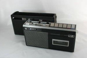
The pictures in this post is what I see in front of me, at the time of writing. I took my Sanyo apart yesterday and I'm writing this also to help myself put it back together. With some help from above, some luck and a lot of patience, I'm hoping to have this set up and running. When - I don't know when, hopefully soon enough. After I finish writing this post, I'm going to clean my MR-4141, measure the belts and put it back together. Then hopefully I'll be able to locate the correct belts online and install them (take the set apart, again... put it back together, again... oh god...).
I'll be posting my results here, to help other nerdy freaks with the urge to repair this piece of old worthless junk.
Before you start, I'd like to warn you that to get to the belts is a NIGHTMARE. The inside of this funky little piece of early 1970s engineering is packed tight on the inside and the cables run from everyhere to everythere and there are a lot of screws holding things down.
Take pictures of everything, write your disassembly process down. Put aside any parts and pieces you find inside, these may be broken bits of plastic or pieces of the original belts. Even though I will measure the belts in my 4141 and post my measurements here, you may want to collect the belt bits for your own measuring - to determine what size replacement belt you will need. Handle belt remains carefully - they are very brittle and fall apart easily. You know, keep them just in case. You never know.
Getting the chassis out.
Remove the back cover by unscrewing the three black screws on the rear (two looong and one short screw). Now take the back off SLOWLY - unscrew the cable going to the bottom of the antenna. On the sides of the set there are strap mounts, remove the screws above them (set standing on the table). Locate the two screws on the bottom right

and left

of the inside plastic chassis. Remove these and now you should be able to slowly lift the chassis off together with the top cover. Do this CAREFULLY - there are wires going from the chassis to the speaker, which is attached to the front of the case.
Removing the top cover.
Take the slider knobs off the volume and tone control by pulling gently. Locate the two wires coming from the chassis to the aluminium trim of the top cover - they should be marked with yellow paint. Desolder these.


Remove the three screws holding the top cover in place - these are at the front of the set (the side you put cassette in).


Now you should be able to lift the top panel off.
Getting to the belts.
..[the "best" part]...
Looking at the rear of the chassis (the side with the printed circuits and battery compartment), on the left you see a printed circuit board. Remove the screw at the top of the board (it has a brown washer underneath it)

At the bottom, the PCB is held by an aluminium plate. The plate's other side is stuck in the plastic chassis, held by one screw - remove it.

To lift the PCB off, "unlatch" the black plate on the left with all the inputs and outputs (remote, mic, aux, ext. speaker) from the main plastic chassis.
Removing the motor cover, flywheel cover and the mains socket.
The motor is located above the battery compartment, on the left. Its metal cover plate is held in place by one screw to which a terminal ring with a green and a black wire soldered to it is attached - remove this.

The wires nearby are tied together with a plastic cable-tie, you can cut this for easier manipulation and better access (BUT NOT THE WIRES!).

Remove the tape from the large plastic part which is the flywheel cover and unbend the metal wire which clamps the connection wires down (this retaining wire is attached to the middle screw).

Now you can move the wires to the side and remove the flywheel cover. You can also remove the flywheel, but you don't have to if you don't want to (it simply lifts off). [I took the flywheel off for cleaning.] At this point you can replace the belt that joins the motor and the flywheel.
To the left of the battery compartment there is the mains cable socket which is mounted on a metal plate that is held by two screws. First, remove the top screw which also holds the retaining wire which passes through a hole in the motor cover [yes, it's insane, I know].

The second screw is accessed from the front (cassette side) of the chassis and it's quite long. In the next picture I have my finger on this screw - remove it and the mains socket together with the fuse holder comes loose.
 Congratulations! You have successfully gained access to the belt center of the machine!
Carefully lifting the wiring and moving the PCB out of the way you can now rejoice and enjoy a heartwarming view of where most of the mechanical action takes place in this portable wonder. The spindle assembly is easily removed by unscrewing of the three screws which hold it in place but don't forget to remove the tape counter belt from the front (provided that you still have a tape counter belt, of course).

Hope this helps - this is as far as I got at the time of writing.
I would also be happy if someone could provide documentation for this machine - service manual, schematic, operating instructions, anything.
Matthew