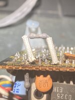
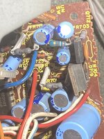
I just pointed out that 704 looks like it could be burnt and never said it was definitely the problem.
Obviously the only way to know for sure is to test them.
It seemed to me that he thought they're all bad or "fried" because they're gray.
Whether or not he can test them is beyond me.
I might have come across as a bit harsh. But that wasn't the intention. Over the years, there's been too many folks showing photos of PCBs and asking, "what's wrong". In my experience, I've come across components that looked mint but which tested short or open. I've seen stuff that looked horrible, but tested in spec. The point is that we simply can't tell by a visual examination to conclude whether something needs replacement or not. There is no visual measure by which we can judge definitively whether something is causing a particular symptom. Ok, as usual, there's always an exeption to the rule, because I've also seen components with clear visual damage (like IC's and power transistors with holes in them and scorching that looks like someone took a blow torch to them.) Needless to say, I'm not talking about those as those are obvious.
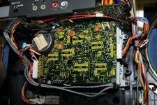
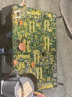
In this case, the fusible resistors in the M90 deck are known points of failure. There simply is no reason to attempt to judge the electrical condition of those 4 or 5 resistors by their appearance. They have long leads and stood off from the PCB so they are easy to check. Anyone who can break down a boombox to extract the cassette deck from an M90, contemplate replacing these fusible resistors and have the necessary tools to do so (soldering iron, solder sucker or desoldering braid, etc) must have a multimeter in his possession right? I mean, a multimeter is probably a far more common tool by a factor of 10 I'm guessing, than a good electronics soldering iron. And if a multimeter is not available, then that should be the first tool to get before opening up one of these TOTL boomboxes, no?
Bottom line, it literally takes only a minute or two to test these 4 resistors and then the truth will be known. No guessing. No contemplating the color, shade, smell or whatever with regards to the resistors, and this was basically my point.