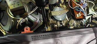
Whenever I take a radio apart, I always take pictures along the way and I highly recommend you do the same and then scroll through the pictures in reverse to make sure you put it all back together and not miss any steps. Although I took pictures for myself, I didn't really take pictures of every step, but will try to explain the parts that aren't covered by pictures.
WARNING: IT IS ABSOLUTLEY IMPORTANT THAT YOU GROUND AND DISCHARGE THE PICTURE TUBE. HERE IS A VIDEO THAT SHOWS HOW TO DO THIS. EVEN THOUGH THIS IS A SMALL TV, IT WILL STILL ELECTROCUTE YOU. DO NOT SKIP THIS VERY SIMPLE AND EASY TO DO STEP!!!!
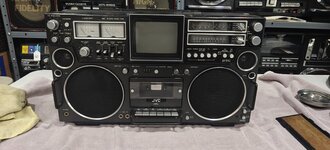
The nicest part about working on a JVC is they color code the screws inside the radio. Each color is only used to remove one component. Chrome screws remove back case, black screws remove the power supply, blue screws remove the deck, ect.
Starting on the back, look for chrome screws with tiny arrows imprinted into the plastic case. There are 9 screws around the outside perimeter and one in the center of the lower back case.

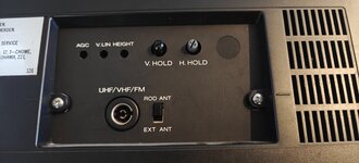
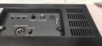
Next there are two screws in the area where the antenna controls are on the back case. These are machine screws and are crucial for making antenna contact and bringing in radio signals.
The back case which houses the battery compartment has a single connector to the power supply on the left near where the power cord connection is made.
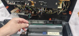
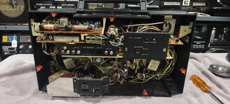
Three black screws remove the power supply along with one plug on the back of the cassette deck.
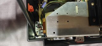
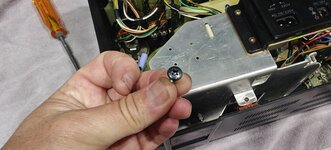
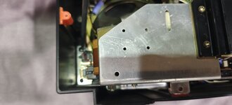
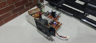
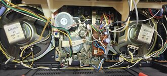
Next remove the four blue screws that hold the amp board in. This is the long board mounted horizonal across the width of the radio. The blue screws go into the cream/white colored plastic bracket and is mounted to the cassette deck structure. Two of the screws have plastic ties that hold the wiring secure. The black square cover for the V Hold and H Hold just unclips and can be set aside.
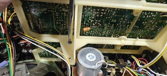
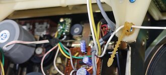
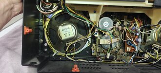
There are three connectors from the cassette deck to the amp board. Two mid board and one on the right end. There is also one large connector on the right side and three more on the left side. There is no reason to completely remove the entire board, it can simply be pulled from the chassis and set to the side with the remaining wires connected.
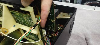
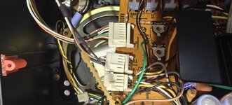
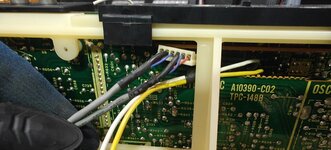
With the amp board out of the way, you can look for the blue screws that hold in the deck, I believe there are six. At this point, you need to move to the front of the radio and remove the cassette deck door. You remove the two screws that hold on the clear plexiglass and carefully release the door from the hinge. Once removed, leave it sitting in place.
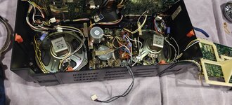
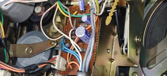
The absolute, most difficult part of this job was disconnecting the cassette deck door from the soft eject mechanism. JVC used a press in plastic button on the front side of the radio that connects the soft eject mech and it is a one time use piece and I felt like it would break if I tried to undo it. I had to remove two small screws that hold the linkage to the door from the inside of the radio at the deck. I did this by removing all the blue screws and lifting the deck out slightly and positioning it so I could get a small screw driver in there. These parts are all plastic, so take your time. After that, the linkage can be worked through the deck and the deck is free from the deck door. I left the deck door in the front case.
WARNING: IT IS ABSOLUTLEY IMPORTANT THAT YOU GROUND AND DISCHARGE THE PICTURE TUBE. HERE IS A VIDEO THAT SHOWS HOW TO DO THIS. EVEN THOUGH THIS IS A SMALL TV, IT WILL STILL ELECTROCUTE YOU. DO NOT SKIP THIS VERY SIMPLE AND EASY TO DO STEP!!!!

The nicest part about working on a JVC is they color code the screws inside the radio. Each color is only used to remove one component. Chrome screws remove back case, black screws remove the power supply, blue screws remove the deck, ect.
Starting on the back, look for chrome screws with tiny arrows imprinted into the plastic case. There are 9 screws around the outside perimeter and one in the center of the lower back case.

Next there are two screws in the area where the antenna controls are on the back case. These are machine screws and are crucial for making antenna contact and bringing in radio signals.


The back case which houses the battery compartment has a single connector to the power supply on the left near where the power cord connection is made.


Three black screws remove the power supply along with one plug on the back of the cassette deck.


Next remove the four blue screws that hold the amp board in. This is the long board mounted horizonal across the width of the radio. The blue screws go into the cream/white colored plastic bracket and is mounted to the cassette deck structure. Two of the screws have plastic ties that hold the wiring secure. The black square cover for the V Hold and H Hold just unclips and can be set aside.


There are three connectors from the cassette deck to the amp board. Two mid board and one on the right end. There is also one large connector on the right side and three more on the left side. There is no reason to completely remove the entire board, it can simply be pulled from the chassis and set to the side with the remaining wires connected.


With the amp board out of the way, you can look for the blue screws that hold in the deck, I believe there are six. At this point, you need to move to the front of the radio and remove the cassette deck door. You remove the two screws that hold on the clear plexiglass and carefully release the door from the hinge. Once removed, leave it sitting in place.

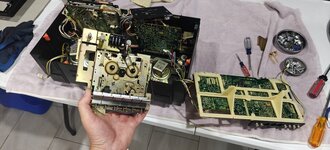
The absolute, most difficult part of this job was disconnecting the cassette deck door from the soft eject mechanism. JVC used a press in plastic button on the front side of the radio that connects the soft eject mech and it is a one time use piece and I felt like it would break if I tried to undo it. I had to remove two small screws that hold the linkage to the door from the inside of the radio at the deck. I did this by removing all the blue screws and lifting the deck out slightly and positioning it so I could get a small screw driver in there. These parts are all plastic, so take your time. After that, the linkage can be worked through the deck and the deck is free from the deck door. I left the deck door in the front case.


