Bluetooth question.

Tinman

Member (SA)
Mar 4, 2019
518
264
63
USA
I've never installed a Bluetooth module before and was considering installing one on my RX-5350.
I found a 9v pin that's only active when the switch (power, radio, line in/phono) is in line in mode so that could turn the module on and off.
Can the module be hard wired into the line in rca connections (R, L & Gnd) on the PCB?
 

Superduper

Member (SA)
You can hardwire it in place at the line-in jack locations but if you don’t have a way to switch the module in/out of circuits, the rca line-in will no longer be of use for aux in purposes because the module will always be active. Secondly unless you know exactly what the 9v power source is that you’re tapping into, be aware that many circuits with voltage might be calibrated for a certain load. When the load changes, the voltage could drop or if it’s regulated, could be overloaded. For example if you look at a schematic diagram, you’ll see voltages of all values everywhere. That’s with all the attached components operating correctly. If the components change or any components have issues, the voltages in those circuits will likely change and it’s this behavior that allows technicians to diagnose circuits using the schematic voltages. So what I’m saying is that you can’t just probe around looking for a certain voltage and presume you can tap there, you need to study the circuit to ensure that it’s actually a stable power rail and not something else like a signal line. Lastly, many if not most Bluetooth modules will exhibit undesirable hum from ground loops that can only be eliminated through the addition of a dc/dc converter/isolator. Keep that in mind. I think mornsun makes some that seems to work well for this type of application. Just make sure you don’t get amplified Bluetooth modules. These isolators and the regulated rail you’re drawing from likely can’t handle such high current conditions.
 
  • Like
Reactions: zafo

Tinman

Member (SA)
Mar 4, 2019
518
264
63
USA
Could the RCA jacks still be used with a cable if the bluetooth module is powered but not in use?
My thinking is that the RCA jacks would be an easy place to solder and are amplified.
Both sets of RCA jacks (inputs and outputs) on this box have their outside collars linked together.
I would assume they'd go directly to ground but on the circuit board there's a huge 2200uf 63v cap connecting the four RCA plug collars to ground.
I don't really understand what that cap does.
If I did use the RCA input jacks, would I connect the Bluetooth module ground before or after the cap?
This pic is from the Panasonic manual but looks to be the same on my Nat/Pan.

1000001026.png
 

Superduper

Member (SA)
Since you are using the line-in jacks, I would solder your ground to the collar, however, if that results in excessive unwanted hum, you can try connecting it directly to ground. Unless you use an isolator like I mentioned in my previous post, you will still have excessive hum however.

If your module is always powered on, the RCA jacks will still work but the signal will be mixed with the module, which probably isn't expecting signals coming from the module. Also your input source may not like it. Lastly, some bluetooth modules have processors that "speak" through the speakers and will probably have a loud "bluetooth connected!" announcement every time. Functionally, you may find that acceptable. However, if it was me, I'd personally prefer to find another way.
 

H3NK3L

Member (SA)
Dec 17, 2020
159
121
43
France
Ok, I'll have to figure out what I want to do.
Thanks.
On a personal note, with line in I use a Bluetooth module on which I deport the on/off switch and find a place to put that switch. Usually don't touch any original pcb or existing powerpins. I simply parallel an ac to usb adaptor to the ac inlet, power Bluetooth by usb and so far on all boxes I used it on that works fine. Only issue is to find a place for the ac usb adaptor and the button. And it makes a hole for the button (and a small one for the USB indicator led, but sometimes I just use the 2 mic holes to put in the indicator leds for Bluetooth. (leaving the original mics inside the box but out of their emplacements.)

I never touch the original voltage supplies, much like Super-duper stated (and he s way way way above my league) : the 12x 9, 6 and other voltages and their original circuitry were designed for the original charge they were made to support.

I only use the original power circuits to replace the original incandescent lights with leds (with the appropriate resistor to get the correct current and verifying that is below the intended current in the original design)

Below is the module I usually use with other parts I use, this particular set was for a Sanyo m9998, the only thing hardwired to an original pcb were the leds for vu meters and dial light and the left right and ground from Bluetooth to din IN. No power taken from the original circuitry except for the led lights replacing a 12v 500 mA mini lightbulb with 4 30mA leds.

Hope this helps, btw Super-duper knows his business!
 

Attachments

Tinman

Member (SA)
Mar 4, 2019
518
264
63
USA
Just to update this:
I connected to the power/radio/line in switch on a leg that's not soldered to anything but only has power (9.5v) when switched to line in.
The power comes directly from the main power transistor confirmed by a continuity test.
Am I overloading it? Possibly.
The only way I'll know is if the transistor overheats/blows.
I wired it to a buck converter which is powering the 5v Bluetooth module.
I soldered directly into the RCA connectors on the board like I mentioned above with the ground soldered before the 2200uf cap.
When trying it out, everything sounded great but leaving the module powered on and using the RCA jacks with a cord , I did notice some noise/interference so I installed a switch between the buck converter + and the module +.
I'm listening to it as I type this and it sounds absolutely incredible.
The bt module is crystal clear, I definitely like it better than a cord and of course not being tethered to the box is nice.
 
  • Like
Reactions: H3NK3L

H3NK3L

Member (SA)
Dec 17, 2020
159
121
43
France
Hello Tinman, nice you got it working.
As for the overload...On some panasonics I ve had, the power/tape/radio/phono-line in switch had the same thing, something like a few unsoldered unused pins, of which some connect to eachother in a certain position - and I ve had the 9v thing as wel (9.something volt) on them. I always figured they kindof used the same circuitry / power pcb for different series and on x or y series its there but just not used. So no idea if it overloads anything , chances are you re well withing margins of error / operation margins they calculated...
Still, and I only speak for myself, I only once used those "unused" powerpins, and always had some kind of interference - and , still on a personnal level, I experiment a lot / sometimes dont do things the most elegant way but I never use the original power supply / powerpins of mess with original pcb (except for experimenting on devices that have already been messed with).

Anyways, great you got it all up and running and running nice and smoothly !!! ENJOY !!!
 
  • Like
Reactions: Tinman

Tinman

Member (SA)
Mar 4, 2019
518
264
63
USA
Hello Tinman, nice you got it working.
As for the overload...On some panasonics I ve had, the power/tape/radio/phono-line in switch had the same thing, something like a few unsoldered unused pins, of which some connect to eachother in a certain position - and I ve had the 9v thing as wel (9.something volt) on them. I always figured they kindof used the same circuitry / power pcb for different series and on x or y series its there but just not used. So no idea if it overloads anything , chances are you re well withing margins of error / operation margins they calculated...
Still, and I only speak for myself, I only once used those "unused" powerpins, and always had some kind of interference - and , still on a personnal level, I experiment a lot / sometimes dont do things the most elegant way but I never use the original power supply / powerpins of mess with original pcb (except for experimenting on devices that have already been messed with).

Anyways, great you got it all up and running and running nice and smoothly !!! ENJOY !!!
I listened to it for at least an hour today without any problems so I think it's fine.
The clarity of it really exceeded my expectations.
The ease of use is great, as long as I leave my added switch in the on position, as soon as I flip the switch to line in/phono, it powers up the bt module and automatically links to my phone in about 15 seconds.
Thanks.
 

Djenzof

New Member
Jul 25, 2023
5
0
1
Bedford
Has anyone used the input from the tape head to a bluetooth adapter?
Is there any reason it wouldn't work?
I know you couldn't use the tape and bluetooth at the same time.
 

Superduper

Member (SA)
The tape heads outputs a very low signal so to compensate for the low output that circuit goes through high amplification to bring it up to line level. Your bluetooth adapter will already output line levels so it would overwhelm and saturate that circuit. Furthermore, anything attached directly to the head lines will likely cause those wires to act as an antenna and you are going to get unwanted noise. I never recommend that connecting 2 signal source together in that way regardless. Bluetooth adapters, especially if mounted internally are likely to be always on, unless you have a way to switch it.
 
  • Like
Reactions: Djenzof

Tinman

Member (SA)
Mar 4, 2019
518
264
63
USA
Somebody here might be able to help you better knowing the models.
Like I wrote above, connecting to the line in jacks worked great for me on the 5350.
 

H3NK3L

Member (SA)
Dec 17, 2020
159
121
43
France
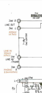
I've been trying to find somewhere line level to link into. Should I be looking after the preamp?
Personally I would start with
1. looking what inputs are available (DIN, microphone, phono, line in/aux,...) from the OUTSIDE
2. testing them with the appropriate cables (you ll need a inverse RIAAA for phono, a jack or rca to din cable for din, either a left and right mono cable or a left+right stereo cable for mics),...
3. find out which one works best

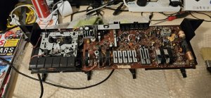
and then 4 : find the service manual for the model before doing anything on the INSIDE

and once the Service Manual in hand (or on screen) take it from there.

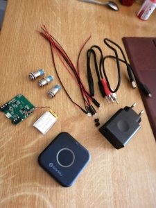
Personally, unless I have a bit of an already pretty much messed with boombox, I wouldnt dig too much into the original circuitry, most often if you want to integrate bluetooth, it suffises to go no further then to solder the correct input to an existing input connector) - and (and thats just personnal), for powering up bluetooth I never use any power from the original circuitry, I add an AC to usb adaptor (parellel to the existing ac input), thus avoiding draining power from a circuit board that wasnt designed for it. Also avoids quite a lot of interference, and has a major advantage : allows to add a proper ON/OFF switch to power on/off the bluetooth module.


What some people do on youtube or others by "bridging" or "bypassing" preamps, rec bars,... may have worked for them on their specific device, but there is no "universal" way of doing things :)