The Saga Continues (blu_fuz 5350)

Status
Not open for further replies.

Superduper

Moderator
Staff member
Ok, I'm starting a new thread since the old one just got too long, and as this thread only will include the fixes without the 200 encouragement posts, it might be more helpful for folks needing to fix a similar type of issue.

This regards the tuner to Joe's (Blu_Fuz) RX-5350 repair thread. You can view or refresh your memory here: https://boomboxery.com/forum/index.php/topic/19914-fixing-a-legend/

As you know, Joe's 5350 had a myraid of issues, the most pressing was a tremendous HUM that left the machine useless for virtually anything. Joe had wanted me to address the hum, and it was a focused request. I never like to accept a "restore" thread on a boombox with 10,000 issues because it ends up to be a huge black hole, sucking up tons of valuable time. So fixing a hum and nothing else? I could live with that. Anyhow, the link above will show how I fixed that issue, after it had been sitting here for a year for me to free up time to look at it.

Now that the hum issue is fixed, wouldn't you know it, Joe wanted me to look at the tuner, which was NOT working at all. No response, no meter action, no sound, no AM/FM or any SW. No nothing. I don't blame him for wanting that fixed. What seemed like something insignificant when faced with a piece of gear that was for all practical purposes, a useless paper weight now seems to be an issue of greater importance since the other issue is now resolved. I great reluctance, I agreed to take a look at it. This thread is intended to document this portion of the adventure now. Hang on!
 

Superduper

Moderator
Staff member
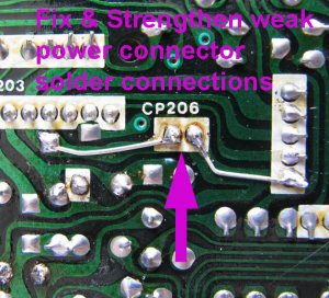
Well, first things first, the boombox would sometimes turn on, sometimes not. Sometimes, it would power up fine out side of the boombox, then not work when inserted back in. Turns out all the handling had done in the power connector solder connections. Fractured them. To beef it up a bit, I had to fix that, and added a little insurance to ensure reliable power. Will be doing a ton of tests and I don't want to deal with a buggy power connector. Removed old weak solder, reflowed new solder onto pads, and added some metal to bridge those two small pins. These two pins power the entire boombox, after all.

RX-5350_b5.jpg
 

Superduper

Moderator
Staff member
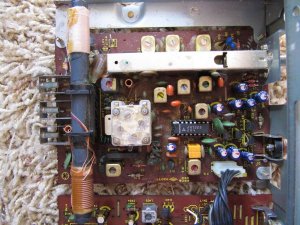
Well, doesn't look so bad at first glance.

RX-5350_b4.jpg


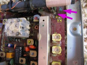
Wait, hold your horses. There's corossion present. Here's some. There's more throughout the board. This is gonna be fun...... NOT.

RX-5350_b6.jpg
 

Superduper

Moderator
Staff member
IC2 is the main tuner module IC. It affects all aspects of tuner operation including AM,FM, etc. This is the first thing to check. It's basically a tuner in a box (IC), but of course not really. Bottom line is a proper functioning IC2 is an absolute must.

Pin 14 of VCC. Should be approximately 7V. I'm getting like under 4V. Hmm, could it be this simple?

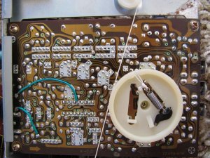
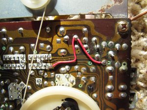
OK, found a discrete resistor R31 which is a 47ohm dropping resistor, supplies power to the tuner IC. Resistor is OK, but the printed traces from board connector to resistor, and from resistor to IC is reading way too high. Gonna jumper the traces, hope this is all it will take. Green wires are the jumpers.

RX-5350_b2.jpg
 

Superduper

Moderator
Staff member
Specs data says Voltage should be 6.2 on FM Setting. Voltage is now 6.56V with new jumpers in place. WooHoo!. Time to stuff guts back in and take a test spin.


------------------------------------------------

!@#$%^&!!?) !!


Rats. Rats. Rats.
Or should I say crickets. Cuz there still isn't any sound from tuner.
 

Superduper

Moderator
Staff member
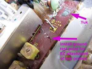
Need to do a serious VR analysis. This requires a good ground and a good tether point makes it much easier so I don't have to use both hands to handle probes. Found a ground location and installed a homemade ground test lead loop to attach cliips or probes. After that, do a test of all semiconductor voltage values.

RX-5350_b7.jpg


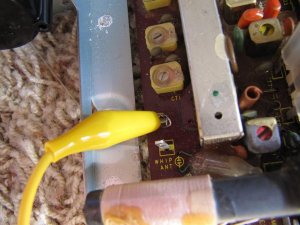
Attaching an alligator clip to ground, this will attach to black probe of meter.

RX-5350_b9.jpg


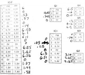
Results of voltage measurements. There are some readings that are way off scale.

volt_measurements.jpg
 

blu_fuz

Well-Known Member
Staff member
Man that corrosion really F'd that thing up. Its been so long I forgot how it looked and the corrosion is really bad.

This turned into a project that was a paperweight, to having sound. Then I got all warm and gooey inside thinking about how good this blaster could be. Shipping it back to me right away would have left it as a line-in only box. That would have been very OK with me, but knowing it was already at your place I figured 'why not ask this super busy guy is he can commit a little more time that he really doesn't have to give'...?

If it ends up that you can figure out the FM issue (i was hoping for easy fix too) then this box will live again for a long time. If it is too far gone (which is an outcome i am ok with) then it will still live on as a line-in blaster until I could score pieces from a parts box.


Thanks again for taking the time away from all your projects. I think this actually kicked you in the ass again to fire up your passion for the blasters. Atleast for now anyway.
 

Superduper

Moderator
Staff member
OK, now that I've had some dinner in me, continuing on.....

Found Resistor (a discrete resistor) R1 to not be connected as traces are toast. Bypassing it.

RX-5350_b12.jpg


From the voltage chart for IC1 (above), you can see that this IC is way out of wack. Here's the general logic: When voltage checks are off, there is a problem. Sometmes it's internal of the component. Most of the time, it is an external issue such as poor trace continuuity, cold or fractured solder joint, or a shorted component, or an open component. This due to ohms law. The voltage data specs are for when the circuit is working as designed. When a factor in ohms law changes, it throws the equation off. That's how we know that there is a problem in the circuit. Generally speaking if the voltage in a supply line is low, then there is too much resistance, or open circuit. If a load circuit is too high voltage, then the load is open or too high resistance. If load circuit is too low, then there is excessive current draw, (short or shorting?). Working from each segment and addressing the issue from point to point, we can hopefully eventually get a fix. As you can see from the chart, the voltages are all over the map. That is not due to 1-problem throwing everything off. That is due to multiple issues. Many times, folks get confused and think that there is one thing causing all the circuitry ills, when there could be many unrelated faults.

So moving onto IC1, we are going to address the out-of-spec pins, follow the schematic and test the appurtenant components and the continuity of the paths from component to component. Forget the trace -- it could squiggle all over the place. If the schematic shows pin 2 of IC1 connected to R2, then there should be continuity of near zero ohms from Pin2/IC1 to one leg of R2 and the approximate resistance of the value of R2 on the other leg. If you don't get proper readings, then there is a problem; fix it, confirm the fix on meter, and move on.


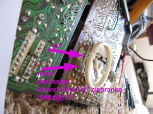
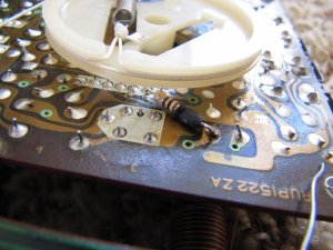
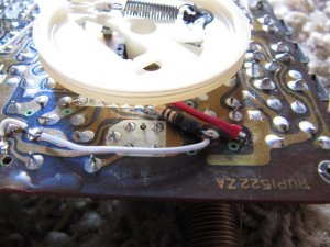
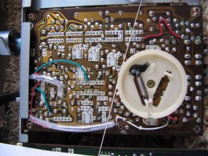
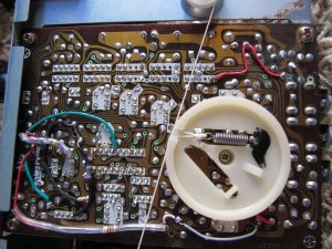
Next image shows problems discovered under the tuning wheel. Not a good place, so I will try to address the issue very very carefully, hopefully avoid having to remove the wheel and the dial cord string.

RX-5350_b13.jpg

RX-5350_b16.jpg

RX-5350_b19.jpg
 

Superduper

Moderator
Staff member
Continuing on.... addressing some voltage issues on Q2, Q4, and Q5 (we are focusing on FM section at this time, as that is the most important for Joe, and probably most folks).


RX-5350_b17.jpg

RX-5350_b18.jpg

As you can see, this board is quite the mess, with degraded traces and failed resistors.

At this time, voltage specs have improved quite a bit. Being a bit impatient, I've decided to see how the progress is translating to real world improvements. So stick the guts back into the boombox to retest. It's the only way since everything needs to be reconnected to see results. Firstly, the harnesses do not stretch that far and having the boards hanging out of the boombox is really risky for possible shorting. There is also a copper shield mat on the bottom of the boombox shell. Mindful that the bottom of the boards are all open foil and solder pads, it's impossilble not to short out the board unless you place something between to insulate it. As I don't want to risk all of the hard work thus far on a piece of cardboard, each test will be by reinstalling the board properly.

Result? FM has been restored! And it sound very good too. Better than most boomboxes even. Sound is clear, loud, and reception is excellent. But still no AM, and no SW. Worse, however, is that FM only comes in, in Mono. No amount of adjustment can stabilize the pilot signal. Should read 19khz on frequency counter. It bounces around 5500 ~ 6200 or so. Oh well, I was hoping that we lucked out, but FM really needs stereo. As Zeddicus 'Zul Zorander always says, "nothing is ever easy." As it is there in magic Midlands, so also is it here. "Nothing (with THIS boombox) is ever easy.

Well, I'm pleased that we've made good progress. Spent a good part of today already, tomorrow we will see what we can do about Stereo FM issue. This tuner board is mono only. This boombox is unusual in that the stereo decoding circuitry is on the mainboard. Highly unusual.
 

howie1976

Member (SA)
My extent of boombox knowledge is equivalent to basic math, you sir are discussing quantum physics here or at the very minimum Chinese calculus. This may be the dumbest I ever felt!😳
 

Superduper

Moderator
Staff member
howie1976 said:
My extent of boombox knowledge is equivalent to basic math, you sir are discussing quantum physics here or at the very minimum Chinese calculus. This may be the dumbest I ever felt!
This thread isn't for everyone, but I know some of the members here like to try fixing so hopefully this will give them some courage to tackle and also some hints and tips on how to approach this type of issue.
 
Wow, was this originally an Ebay 'Everything works fine' box?

Local member Dan has a 5350 that has power but nothing else, no deck, no tuner, no line in

Another local member, Scotty has a 5350 that recently died with no functions working!!

Are these a troublesome model? Seems like there are quite a few out there with multiple problems.

James.... :-)
 

howie1976

Member (SA)
Superduper said:
This thread isn't for everyone, but I know some of the members here like to try fixing so hopefully this will give them some courage to tackle and also some hints and tips on how to approach this type of issue.
Don't get me wrong, I'm fascinated by your posts. You are dropping some serious knowledge. Unfortunately for me, I am in my infancy stage in my new found hobby.
 

Superduper

Moderator
Staff member
jimmyjimmy19702010 said:
Are these a troublesome model? Seems like there are quite a few out there with multiple problems.

James.... :-)
James, when this model is working properly, it is a terrific sounding boombox with massive power. Service manual lists power output as 40w max (20w x2) RMS. Depending how much you believe manufacturers specs, this is probably a bit more than an M90. Not sure which is more louder as I wouldn't want to be listening to either at full tilt. However, this model is definitely worth coveting.

Now as far as troublesome, as with many complicated boombox models this vintage, it requires a double sided board. Modern boards use copper on both sides. Back then, only the bottom (foil) side was copper. the top side was formed by printing the traces using conductive material. That in itself isn't necessary terrible since potentiometers have been printing traces for ages. Also, in addition to printed traces, they also printed resistors too, so much of the top side resistors will not be discrete components. Whether the top side of the board is more exposed to environmental contaminants or introduced by the user (spills, etc) or whether it is lacking the protective oils possibly found inside the pots, or not as well sealed as pots, whatever.... they are often prone to degradation. That is where some of the problems manifest. However, I would not say this problem is isolated with this model or even this manufacturer. I have seen it in other boomboxes too so it's not an idiosyncratic issue with this one and a well cared for example having been kept in a well conditioned environment will still be in good electrical shape.

However, there is one issue that is common to this model (but not Joe's) is that the power switch is easy to fail, it is a weak link. The way it works is that the function selector switch (looks like a record bar) has a lever on the side that slides back/forth as you move it. This lever trips a micro leaf switch as it slides from the off position to the radio or line position. I would say better than 1/2 of the 5350's might have or may soon has this issue. As you might can guess, the switch is likely unobtanium now so a more modern switch will need to be rigged, mechanically as well as electrically. On the positive side, at least Panasonic had the good sense to have the power switching function handled by a power switch and not the function switch, as many boomboxes do. The reason is that the function switch internal contacts aren't really rated for power switching duties and they soon arc/wear out. The only way to repair those is to remove those 40 pin switches, disassemble it, hope you don't mangle many feelers in the process, and have a donor switch (of same or similar feelers) to transplant. I would much prefer to have the external switch fail than an internal one.
 

trippy1313

Member (SA)
Question, so will all the jumper wires essentially replace the board traces, or are they there for testing? I'd assume that's the easiest way to fix it and best way to test is with the jumpers?

Quite a complex looking setup. Fun read.
 

blu_fuz

Well-Known Member
Staff member
In all that reading I believe I read that you got FM mono to sing again. Unbelievable, that is great news considering the condition of the boards.


Yes, Trippy - all of these jumper wires and new soldered in resistors (in tubing) will stay with the boombox forever. It is the only way it can function.


Jimmy, this 5350 I bought it with the description saying 'have no cord to test, but something is wrong with it. Makes a buzzing noise when turned on'.


Now, I am always willing to take a chance on a boombox that has an issue that the seller has not pinpointed. There is always a good chance that it is something simple and I have 95% of them do work out to be simple. The research I did before buying it in this 'buzzing' condition was leading to that it could need a full re-cap to get it going again and I figured it was still very worth it to try.

I did not know that the tuner was doing nothing, dead, flatlined, etc..... shoot, I really didn't even notice until I was knee deep into the repairs I already did and Norm noticed it when it got to him that the tuner was infact totally dead. Not a good sign.
 

Superduper

Moderator
Staff member
trippy1313 said:
Question, so will all the jumper wires essentially replace the board traces, or are they there for testing? I'd assume that's the easiest way to fix it and best way to test is with the jumpers?
Trippy: the jumpers are replacements for the original traces. You need to understand that the original degraded traces are all topside and of a carbon-epoxy type of material that is not solderable. Therefore, the only way to repair failed traces of this type is to do it from below. Also, you will note that not all jumpers are just wires. Many of them are resistors that span pad-pad by their leads (insulated). Luckily none needed wire extensions since that would not be ideal as component leads are not designed for constant flexing like wires are, and unless wires are affixed to both ends of the resistor, the fixed lead will flex from the movement permitted by the wire ends, resulting in future metal fatigue and eventual failure. Also, many of the top traces and resistors are not necessarily failed, but actually degraded in the form of increased resistance. Jumping degraded traces is no problem since we want the lowest resistance as possible but resistors are a different matter for leaving them in circuit means we would need to calculate a custom resistance (rather than replacing with orig value) since leaving the orig resistor in place results in parallel resistance paths. Sometimes if the resistor has degraded to where the resistance is much higher than normal (for example, 500k instead of orig 22k), it is acceptable to leave it in place since the total resistance would only change by a very small fraction. In this case, a 22k resistor in parallel with a 500k resistor would result in a total circuit resistance of 21.07k, a negligible variance. In other cases, where the residual resistance would adversely affect the total circuit resistance, we need to remove and isolate that part of the circuit. I do this by using a 1/16" twist drill with finger force to ream out the via (tunnel that connects the top and bottom boards together electrically).


blu_fuz said:
In all that reading I believe I read that you got FM mono to sing again. Unbelievable, that is great news considering the condition of the boards.
Joe, indeed FM has been restored, but only in Mono. After reinserting the guts, I found that while FM worked, it did not work well. On another 5350 I worked on years ago, the IC2 was bad and replacement restored function. Since I already installed a IC socket for that IC to facilitate testing of the appurtanent components, it was easy enough to pop out the IC and install a replacement. Luckily, I found my stash (still got a couple more) and after replacement, FM was strong. That IC is panasonic AN7223. Still in mono, so today we will see what's up with the FM decoder section. The stereo adjustment pot does nothing right now.
 

Superduper

Moderator
Staff member
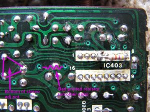
OK, found the stereo adjustment pot, it works fine. But that pot has another fixed resistor in series with it which has partially failed. That will definitely affect the ability of the pot to allow adjustment of stereo. Now, I'm excited and hope that is the "only" cause of the FM stereo issue.

RX-5350_b22.jpg


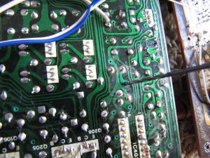
The original resistor needs to be isolated from the circuit. A 1/6" drill bit operated with only my fingers was enough to break the via connection. Test with meter after to confirm orig resistor is isolated.

RX-5350_b23.jpg


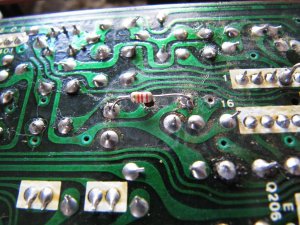
Here is new resistor. Note drilled out via under the resistor body. The other via hole is left untouched since it's no longer connected to anything anyhow.

RX-5350_b24.jpg

Will retest now to see if we lucked out on fixing FM Stereo issue.
 
Status
Not open for further replies.