Realisstic SCR8 power issue

Status
Not open for further replies.

Superduper

Moderator
Staff member
Docs, as in the past, I can give you hints and clues, and the actual hands on troubleshooting is up to you.

It sounds like one component, connection or wire is shorted.

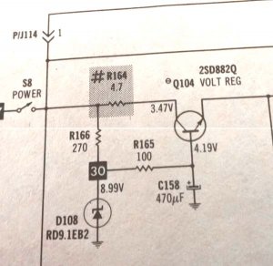
Presuming you've already checked Q104 to ensure it's working properly, disconnect emitter of Q104 and check voltages at Q104 as well as D108. With eQ104 disconnected, restore power and see if R164 holds. If yes, then check voltages. If voltages are out of range, then correct the issue before proceeding. You have an issue at the regulator.

If voltages appear proper, then check all of the bypass caps downstream fed by that 3.46v regulator for a short to ground. There are a lot to check but you can check them quickly in circuit simply by using a DMM on the ohms range across the cap leads. Before checking, it is a good idea to discharge any caps that will be tested by jumping the 2 leads for a moment. This provents potential damage to your meter by residual charge on the caps. Any caps that are in series with a good working resistor is probably, for the purposes of this test, not the likely culprit. You should not read low ohms across any of the caps. This is the easy part. It goes without saying that when checking circuits using the ohms function, first DISCONNECT the power. You are NOT taking resistance measurements live.

If all caps test good, then any circuit downstream should be checked for short. Using schematics, highlight any circuits fed by that regulator. From there, check each sub circuit to see if any of the transistors, caps or resistors are shorted. Generally speaking, any circuit in series with and downstream to a resistor that has tested good is probably safe to presume not culpable unless the resistor is low ohms. The reason is that R164 is only 4.7R. Therefore, a circuit downstream that runs through a good 100R resistor will not draw enough current to toast R164. This clue shall allow you to isolate and eliminate possible paths as likely good.

Good luck.

BTW, is that schem one that I sent to you? If so, please respect our prior agreements not to share, especially hi-res examples.
 

docs

Member (SA)
Thanks Norm, will undertake tests.
The schematic links to your previously posted pic from our previous thread so assumed ok.
Is the 4.7 resistor a fusible one do you think since it is shaded and has a #?
 

Superduper

Moderator
Staff member
The documentation does not identify it as fusible, but it does specify the following:

4.7R 5%, 1/8W carbon film.

The # and shading indicates that it is a critical part and must be replaced with an equivalent item. You may want to make sure you get replacements with the same specs. Going over-spec might render the "fusible" feature ineffective. In other words, if you go with the more common and standard 1/4 watt resistors, or using metal film instead of carbon, then the resistor either might not let go soon enough, or even at all before damage to other components occur. As always, with resistors that are designed to go up in smoke during overcurrent conditions, I suggest you mount them slightly elevated off the board to prevent the board from scorching which could damage the board.
 

docs

Member (SA)
Thanks Norm.

With eQ104 disconnected, the resistor is still burning out. Confirmed by disconnecting the collector and the resistor NOT burning out.
Tried with a new Q104 in place and it does the same thing and I think the Q104's I have are working fine.

R166 tests as 270ohms and R165 tests as 100ohms.
Tested D108 and C158, both are good.
*scratches head*
 

Superduper

Moderator
Staff member
How did you test that diode? It's a zener and typical dmm diode tests don't involve enough voltage to meet the avalanche point. Also how did you test the cap?

Maybe Try with q104 in circuit, emitter leg lifted, test resistance from r164 to ground. If you are getting very low resistance, you have a short. Could be a solder bridge, or something very simple. The thing is with emitter lifted, you have essentially removed the entire load from the circuit. Only the regulator circuit remains and you are blowing that resistor with only the regulator components in place.... The problem is right in front of you. So take a step back and review the schematic again. With emitter lifted, all of the loads are disconnected right? So something is not right.

----------- edit -----------------

Dave, what transistor is that you have in there, does it look original or does it look like it's been messed with? Counterfeit parts have on too many occassions, created huge diagnostic headaches. What should have been simple diagnostics turned out to be hair pullers and lots of wasted diagnostic time only in the end to find that the parts are counterfeit and spec differently from orignal (or have wrong pin outs). I have even heard of PNP's being tested as being NPN's (and vice versa) internally. MCM have been known to sell some counterfeit parts so if you got replacements from there, you might want to verify what you have. Or.... did you get from eBay? If so and from China, you really should verify. Replacement should be 2SD882Q

In any event, the regulator circuit is rather simple. You can even recreate a simple regulator like that on a breadboard, with a zener diode, a NPN transistor, a couple of resistors and the cap and you'll see that it works. Now, if you simply can not figure it out, as a last resort, you can nix that part of the circuit and create your own voltage regulator to shoehorn in there. But it's best you fix what you have. Actually since you have replacement parts at your disposal, you might even want to use a couple of resistors, the transistor, the zener diode and make the circuit on a the breadboard to confirm that it works properly with the parts you have. With the solderless plug in type of board, it would take like 1 to 2-minutes to build that circuit.

Here is a sample regulator circuit, and the documentation even provides a chart for what resistors to use to create a 3.6V output. http://www.ti.com/lit/ds/symlink/lm723.pdf
You would probably want to use the regulator in conjunction with an external transistor. But if you go to that route, it wouldn't be any simpler than just repairing what you have.
 

docs

Member (SA)
Hi Norm, I tested the diode the standard way both in and out of circuit to try and ensure that it was not opened and used the DMM in diode test mode either way around. It allowed flow one way but not the other. the cap is a little more difficult to test since I don't have the correct meter but it was grounded properly and I also tried a brand new cap in there.

I bought these replacement transistors but the original tests out the same as the new ones do and i believe it is an original which has not been messed with previously.
I will borrow a breadboard from my son and test the components in that to try and isolate.
 

Superduper

Moderator
Staff member
Question: is that transistor have solid epoxy body or does it have any metal that could contact the heat sink or mounting screw?

Also, can you check resistance (powered down) between q104 emitter to ground and collector to ground, let me know what you get?
 

docs

Member (SA)
Yes the transistor has a metal side for contact with the heat sink.
eQ104 to ground reads 1,100ohms (1.1k) and cQ104 to ground reads 816ohms desoldered (to the trace) but reads Zero ohms when soldered.
 

Superduper

Moderator
Staff member
Ok when I look at the schematic, aside from the load (you said 1.1k) from emitter to ground, there is no other path to ground except through d108 and c158. And since you said that both checks out, those paths don't seem likely. Additionally either of those paths go through resistors as well as the collector-base junction of q104 which should not conduct if q104 is working properly.

Here's the 2 possible scenarios of what I think might be going on:

1) the collector of q104 is probably tied to the metal die (as in most power transistors). You can check to confirm with one of your extra transistors. In this case, I'll bet the heat sink is grounded, again easy to check. As soon as you fasten the transistor to the heat sink, you've essentially grounded the collector lead (huge short that will toast anything). Proper transistor mounting in these cases involve an insulator which electrically isolates the transistor body from grounded heat sink.

2) if that is not the case, then you either have an issue with the pcb or a stray ground. The fact that you are reading zero at cQ104 tells me that this particular pad is indeed grounded and if the ground isn't introduced by the transistor/heat-sink mounting configuration, then you need to carefully search for bridged solder joints etc. remove all of the regulator components if necessary and check that pad for ground while reinstalling the components one by one to find the short. It shouldn't be that hard.

However, I suspect that the issue is #1 above and not the pcb since the resistor holds intact when collector of transistor is isolated. If you unfasten q104 from the heatsink, I suspect you'll find that cQ104 is no longer grounded and probably can power up for a test. If yes, then order a proper TO-126 mica or silicone insulator and screw kit, recheck cQ104 is isolated from ground after mounting and call it fixed.
 

docs

Member (SA)
Norm, thanks.
I confirmed that the collector of the transistors is tied to the outer metal section designed to connect to the heatsink. Upon moving the transistor away from the heatsink while still in circuit results in a power up without burning out that R164 as you correctly assumed.
I've ordered the proper resistors for both R164 and R264 which was also toasted so am awaiting them arriving.
I've also just bought the TO-126 MICA washer so hope to receive them all soon and report back on another Superduper fix.
 

Superduper

Moderator
Staff member
Before powering up, I caution you to please do confirm that as installed, c-Q104 is no longer shorted; just in case the mounting screw somehow does contact the metal die, which of course will once again short the collector to ground even if the die itself is isolated from the heatsink.

For info on mounting transistors, (good for you to keep as reference), view these guidelines by on-semi electronics:

http://www.onsemi.com/pub_link/Collateral/AN1040-D.PDF

==================================================

For those folks trying to follow along, this is the circuit that Dave is speaking of. Note that there is an error on the schematic. The voltage specified at the collector is wrong, should be around 18v and the indicated value should be for the emitter instead. The remainder of the diagram is cropped as they are irrelevant to the problem, and for clarity on where to focus attention.

scr-8_regulator.jpg
 

docs

Member (SA)
Thanks again Norm, great advice as ever.
Once the stuff arrives I'll be sure to check the resistance on cQ104 and will see if i can insulate the screw with a grommet of some sort.

True that the collector has straight 18v (or marginally under) while the emitter should be 3.47v, thanks for pointing that out.
 

docs

Member (SA)
Installed a mica washer and resoldered Q104 then tested the resistance across all pins which showed good and no short. Awaiting a 2.2ohm and 4.7ohm 1/8w resistor to finish putting this one back to use.
 

docs

Member (SA)
The resistorss finally arrived so I fitted both the 2.2ohm and 4.7ohm which restored power.
Sadly there is no power to the deck so I thought it may have been the same issue, so I replaced Q204 and installed a mica washer to no avail. The voltage on the cQ204 is only around 13.5v. The voltage on R264 is shy of 18v then goes down to 13.5v on the lead connecting to cQ204.
 

Superduper

Moderator
Staff member
That new issue is obviously unrelated. That all these transistors have no insulators disturbs me and suggests that things have been messed with before. Who knows what else has been done.

In any event, those measurements don't give the whole picture. You need to provide more voltage measurements for us to form any kind of definitive opinion. Please provide all voltages at Q204 b/e/c and TP# 29. Did you confirm that R264 (2.2R) is not blown or otherwise changed to very high ohm? You can test that in circuit (powered down). Should read 2.2 or less.

Actually, based upon your voltage drop (18 - 13.5 = 4.5), the current computes to over 2-amps through R264 if R264 is still 2.2R. Unless that resistor is the size of your thumb, then I suspect that it is blown or way out of spec. Replace it but you should also check to make sure there isn't something else which caused it to blow in the first place. Maybe check and ensure that the motor is not drawing too much current.
 

baddboybill

Boomus Fidelis
I know it may be a long shot but check micro switch on deck for short as well. Had one on my mini Sanyo that shorted and caused issues in deck 😉


Bad Boy Bill
 

Superduper

Moderator
Staff member
Yep, a shorted switch (to ground, not across the contacts) would blow that resistor pronto, lol.
 

baddboybill

Boomus Fidelis
Yep, a shorted switch (to ground, not across the contacts) would blow that resistor pronto, lol.


Yep that's how mine was. The plastic insulator was worn down and the rivet that held the insulator on kept grounding


Bad Boy Bill
 

docs

Member (SA)
Thanks guys, managed to restore deck power by checking the deck mechanism and resetting it then replacing the 2.2ohm resistor.
Now onto the sound missing in right channel issue lol
 
Status
Not open for further replies.