Big Ben DOA Sorta

Status
Not open for further replies.

=ml=

Member (SA)
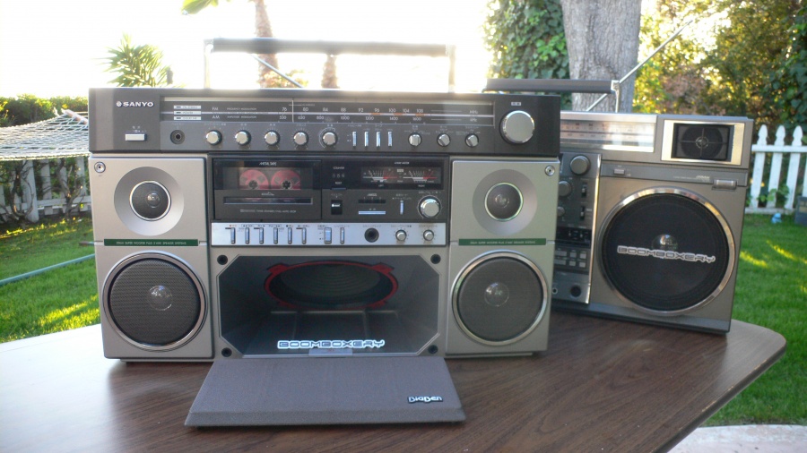
I finally unboxed my Big Ben (MR-X20) this weekend, and while it was sold as working it only sorta does: :sad:

* Radio does not work
* Power light does not illuminate when power button is pressed
* All tape functions work but no sound
* Tape deck runs off battery or AC
* Tape deck button LEDs come on when power switch is off, and turn off when power switch is on

I De-Oxited the switches from the front (haven't fully opened it yet).

The pictures of it showed the power light illuminated and the seller claimed the radio worked.

Even though well packed, I think it got rough handled at some point because one of the mounting posts was broken and the same side of the bottom of the case was misaligned.

Thanks for any ideas on how to get it booming again! I want to have it blastin' in time for the mini-meet at Chris'.

Here it is:
l1110648.jpg


Go!

=ml=
 

mrp32

Member (SA)
Nice Big Ben :-)
Sounds like it's stuck in sleep mode :hmmm: maybe a problem with the power switch
Does the radio work with power button off when tape is playing?
Hope you can sort it
 

=ml=

Member (SA)
mrp32 said:
Nice Big Ben :-)
Sounds like it's stuck in sleep mode :hmmm: maybe a problem with the power switch
Does the radio work with power button off when tape is playing?
Hope you can sort it

Thanks :)

What would cause it to get stuck, and more importantly, how can I wake it up?

Radio does not work with any configuration of buttons or power source. In fact there is no sound at all - no hiss, no scratching, no nothing - just a deafening silence. :hmmm:

Go!

=ml=
 

=ml=

Member (SA)
The mystery is solved...

While at Chris' for the mini-meet, I took apart the Big Ben to fix it. I figured with all the great blaster knowledge there we could get it working again. As Patron was helping me separate the power cord from the main PCB, he noticed a crack in it. Upon further inspection, we determined what the issue was: an approximately 3 inch long crack in the PCB beginning right at the power molex connector and continuing diagonally into the middle of the PCB. :'-( :'-( :sad: :sad:

It appears that the box was dropped during shipping and the Big Ben back shifted enough to crack a mounting post and since the main PCB is stabilized by the back, when it shifted the circuit board did too - crack. :thumbsdown: :thumbsdown:

So one mystery has been solved and another now begun. Where can I find a Big Ben main PCB (would a Super Woofer one work too?) Alternately, is it possible to repair the current one, and if so how? :hmmm:

My camera batteries died so I couldn't take any pictures or video of the meet at all, let alone the cracked PCB. I can't remember if anyone took pictures of the crack, but if you did, please upload them to this thread. Thanks!

Go!
 

BoomboxLover48

Boomus Fidelis
It needs lots of patience. Use jumper wires to reconnect the broken pcb lines. Have a good plan before you start. Take pictures and make sure you reconnect it the right way. Check continuity before and after each line repair. If possible connect jumpers at points that will not heat up a component. Use heat sinks wherever you can to avoid heating components. It is good to use shrink wraps on each jumper ends to avoid short circuit.
 

Lasonic TRC-920

Moderator
Hey Miles,

That was really painful to see. That crack might be fixable. I would post up in the WANTED SECTION and maybe one will pop up. In the mean time, you have nothing to loose by trying to fix it. I would pull the board out so you can have complete access to it and take a ton of up close up hi res pictures and maybe a generous member here could open the back of their Big Ben and take hi res pictures of the same area and you could begin the long tedious process of soldering jumpers between everything. As long as no diode's are broken, it might work. The hard part would be getting the PCB back in position again, because it wasn't flat, it was crossed up. If you need any help let me know. I know how to solder pretty well, so if need be, I can help with that.

Best of luck :yes:
 

Jboogie2384

Member (SA)
BoomboxLover48 said:
It needs lots of patience. Use jumper wires to reconnect the broken pcb lines. Have a good plan before you start. Take pictures and make sure you reconnect it the right way. Check continuity before and after each line repair. If possible connect jumpers at points that will not heat up a component. Use heat sinks wherever you can to avoid heating components. It is good to use shrink wraps on each jumper ends to avoid short circuit.


I have to do the same thing to jvc rc-55 I got a while back. The left speaker is faint due to the pcb board being cracked as well. Ill have to do the jumper idea in my box as well. It's not bad and it's a short "jump" so hopefully I should be able to get it up and running.
 

BoomboxLover48

Boomus Fidelis
Jboogie2384 said:
BoomboxLover48 said:
It needs lots of patience. Use jumper wires to reconnect the broken pcb lines. Have a good plan before you start. Take pictures and make sure you reconnect it the right way. Check continuity before and after each line repair. If possible connect jumpers at points that will not heat up a component. Use heat sinks wherever you can to avoid heating components. It is good to use shrink wraps on each jumper ends to avoid short circuit.


I have to do the same thing to jvc rc-55 I got a while back. The left speaker is faint due to the pcb board being cracked as well. Ill have to do the jumper idea in my box as well. It's not bad and it's a short "jump" so hopefully I should be able to get it up and running.
If it is speaker lines you can use the internal wires of the home telephone wire as jumper wires. Those gray wires contain 4 wires inside. There are 4 wires yellow, blue, red and black. The gray cover can be easily removed once you make straight cuts on ends, scribe along the length and pull it. I will post pictures of those later when I get home. Actually these wires came so handy for my jumper wire jobs.
 

Jboogie2384

Member (SA)
I have to do the same thing to jvc rc-55 I got a while back. The left speaker is faint due to the pcb board being cracked as well. Ill have to do the jumper idea in my box as well. It's not bad and it's a short "jump" so hopefully I should be able to get it up and running.[/quote]
If it is speaker lines you can use the internal wires of the home telephone wire as jumper wires. Those gray wires contain 4 wires inside. There are 4 wires yellow, blue, red and black. The gray cover can be easily removed once you make straight cuts on ends, scribe along the length and pull it. I will post pictures of those later when I get home. Actually these wires came so handy for my jumper wire jobs.[/quote]

Damn that's an great idea Boom!! I also have a lot of CAT5 wire laying around as well. Great tip. :thumbsup:
 

BoomboxLover48

Boomus Fidelis
Jboogie2384 said:
I have to do the same thing to jvc rc-55 I got a while back. The left speaker is faint due to the pcb board being cracked as well. Ill have to do the jumper idea in my box as well. It's not bad and it's a short "jump" so hopefully I should be able to get it up and running.
If it is speaker lines you can use the internal wires of the home telephone wire as jumper wires. Those gray wires contain 4 wires inside. There are 4 wires yellow, blue, red and black. The gray cover can be easily removed once you make straight cuts on ends, scribe along the length and pull it. I will post pictures of those later when I get home. Actually these wires came so handy for my jumper wire jobs.[/quote]

Damn that's an great idea Boom!! I also have a lot of CAT5 wire laying around as well. Great tip. :thumbsup:[/quote]
I am glad you liked my suggestion of using those wires. :yes:
 

kraftmatic

Member (SA)
Hey Miles, I can bring my BigBen over or loan it to you if you need a reference unit. Let me know if you want to have a go at it together and see if we can get it back to life.
 

=ml=

Member (SA)
kraftmatic said:
Hey Miles, I can bring my BigBen over or loan it to you if you need a reference unit. Let me know if you want to have a go at it together and see if we can get it back to life.
Thanks for the generous offer Owen! :thumbsup: :-)

I may take you up on it. I'll let you know...

Go!

=ml=
 

Lasonic TRC-920

Moderator
=ml= said:
kraftmatic said:
Hey Miles, I can bring my BigBen over or loan it to you if you need a reference unit. Let me know if you want to have a go at it together and see if we can get it back to life.
Thanks for the generous offer Owen! :thumbsup: :-)

I may take you up on it. I'll let you know...

Go!

=ml=

That's a real good idea.... :yes: Great place to steal some parts if you need'em :lol: :lol: :lol: :lol: :nonono: :-P
 

kraftmatic

Member (SA)
Lasonic TRC-920 said:
=ml= said:
kraftmatic said:
Hey Miles, I can bring my BigBen over or loan it to you if you need a reference unit. Let me know if you want to have a go at it together and see if we can get it back to life.
Thanks for the generous offer Owen! :thumbsup: :-)

I may take you up on it. I'll let you know...

Go!

=ml=

That's a real good idea.... :yes: Great place to steal some parts if you need'em :lol: :lol: :lol: :lol: :nonono: :-P

Hmmm, now I'm thinking twice about that offer... :-D
 

ledmeter

Member (SA)
I would totally have a go at fixing it. Even though it's time consuming, it'd be so rewarding to see it come back to life. I've done it before, I just traced the circuit back to the nearest solder point on each side of the break, then use a piece of wire (the kind that is soldered all along inside the sleeve) about the same length as the circuit. It's painstaking but once you're on a rhythm it's easy.
Good luck! :yes:
 

stormsven

Member (SA)
Dont panic dude. Cracked board is not so big issue. Quite easy to fix for a handy tech guy.
The boomer looks so clean. Im sure it will boom soon again :thumbsup:
 
Status
Not open for further replies.